First Steps to Improving Low-Power Optical Signal Detection


Please Wait
What are some first steps to improving power measurements of low-power optical signals?
Measurements of low-power optical signals can be improved by minimizing ambient light, blocking reflected and scattered light from reaching the power sensor (photosensor), ensuring the beam spot remains within the sensor's active area, optimally configuring the power meter's dynamic range, and performing the power meter's zeroing operation under ambient light conditions. The objective is to minimize the influence of spurious light sources on the power measurement, ensure that the sensor continuously measures the power delivered by the entire beam, and optimally configure the power meter for the experimental conditions.
Ambient Light
Ambient light is the light provided by all sources other than the optical system's light beam(s). In many cases, room lights are the greatest contributor to ambient light, but significant amounts can come from computer screens and other monitors, as well as light emitting diode (LED) indicators on instruments. A frustrating aspect of ambient light is that it can vary with the movement of the operator during the measurement, blinking of indicator lights, and screen display changes.
The effects of ambient light can include artificially inflating power readings, interfering with the detection of low-power signals, and saturating the sensor. When the sensor is saturated, the sensor outputs a signal near or at the maximum possible level. A sensor saturated by ambient light either cannot respond, or will respond poorly, to the additional power in the incident optical signal. The desired signal may also be undetectable if ambient light levels are low enough to avoid saturation, but high enough that the signal's contributed optical power is negligible in comparison.

Click to Enlarge
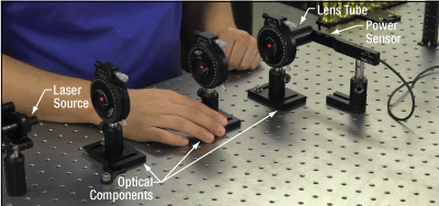
Figure 1: In the setup shown above, an SM1 lens tube is attached to the S130C optical power sensor, with the assistance of an SM1A29 thread adapter. The power sensor is positioned so that the exposed end of the lens tube nearly touches the transmission side of the nearest optical component. The lens tube helps isolate the power sensor from unwanted light. In a Video Insight, this setup was used to demonstrate a method for aligning a polarizer to be 45° to the plane of incidence.

Click to Enlarge
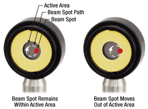
Figure 3: The beam spot can move across the power sensor due to alignment or normal operating conditions. The entire beam must be within the active area of the power sensor to accurately measure power. Circular movement of the beam spot during the measurement is illustrated above by the dashed-white circle. Ideally, the beam spot remains within the active area of the sensor (left). If the beam occasionally extends off of the power sensor (right), it can be hard to figure out that the associated power readings are artificially low.

Click to Enlarge
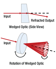
Figure 2: The front and back faces of the optic illustrated above are not parallel. Rotating the optic around the optical axis changes the direction of the transmitted beam. This type of situation can result in inaccurate measurements of optical power, as illustrated in (Figure 3).
Options for minimizing ambient light include turning off the room lights, installing the setup in a light-tight enclosure, covering monitors or turning screens to face away from the sensor, and / or turning off LEDs or covering them with black tape. Attaching a lens tube to the sensor housing as shown in Figure 1 can also be effective in reducing the ambient light incident on the power sensor.
Stray Light
Light beam(s) in the system can scatter, refract, and / or diffract from optics and mechanical housings in a setup, producing stray light. Stray light paths can be difficult to predict and block, since this light may interact multiple times with different optical elements and overlap the primary beam path. The effects of stray light on the measurement of the desired signal are similar to the effects of ambient light.
The best approach for blocking stray light depends on the beam trajectory and the setup, and often a combination of techniques are used. It is easiest to eliminate stray light that does not follow the beam path. Reflections can be directed away from the optical path by rotating optical surfaces away from normal incidence with the incident beam. However, this is only an option when the application is not sensitive to the optic's nonzero angle of incidence.
When the angle between the signal and stray light paths is reasonably large, a lens tube attached to the sensor (Figure 1) can block the stray light. If there is only a small angular difference between the stray light and signal paths, one option is to position an iris in front of the sensor to block the stray light while allowing the desired signal to pass through. Another option is to move the sensor farther away. With enough distance, the separation between the desired signal and the stray light will increase such that the stray light will either no longer be incident on the power sensor or will contribute negligibly to the power measurement.
Power Sensor Size and Beam Walk Allowance
The measured signal power will be artificially low if the diameter of the signal beam is larger than the active area of the power sensor. Note that the 1/e2 beam diameter, which is typically measured and specified for Gaussian beams, includes ~86% of the beam power. The diameter that encloses 99% of the beam power is a factor of ~1.5 larger than the 1/e2 diameter.
Ideally, the beam would be aligned so that it is centered on the active area of the sensor. If the beam is not aligned with the sensor's center, the risk of measurement errors increases. The power measurement will be low if the beam spot extends beyond the sensor's active area. If part of the beam overlaps with the active area, it may not be immediately obvious that there is a problem, since some signal power will be measured. Due to this, checking the overlap is recommended before taking measurements.
Imperfect overlap between the beam and power sensor might be a transient problem if the beam spot on the power sensor does not remain completely stationary during the measurement procedure. For example, the beam spot may wander if the measurement requires rotating an optical component around the optical axis (Figures 2 and 3). This is a particular concern if the front and back faces of the optic are not normal to the beam path. It may be possible to accommodate a moving beam spot by choosing a large-area power sensor.
Signal Within the Power Sensor's Dynamic Range
The sensor's dynamic range refers to the span of incident optical powers, minimum to maximum, compatible with the sensor. An accurate measurement requires the signal power to be within the sensor's dynamic range.
The noise floor typically defines the minimum detectable optical power level. The noise floor is the signal power reported by the power meter when absolutely no light is incident on the power sensor. The signal results from noise in the complete detector system, which includes the power sensor, power meter, cables, amplifiers, filters, and all other components. The incident signal will not be detected unless its optical power is sufficient to provoke a response exceeding the noise floor. Measurement accuracy may be poor when the signal response is close to the noise floor. A signal that is close to the noise floor has a low signal to noise ratio (SNR), which is the power in the desired signal divided by the noise power.
Power sensor manufacturers often specify maximum incident power levels below a threshold called the saturation intensity. Operating well below the saturation intensity threshold is recommended, since as the threshold is approached the sensor response becomes nonlinear and can result in power measurements that underestimate the power incident on the sensor. This can result in beam powers that unintentionally exceed applications' maximum operating power limits and is a significant concern. In the case of incident powers above the saturation intensity, the measurement reading is often a constant maximum value. One way to check for saturation conditions is to increase the signal power slightly while monitoring the power reading. If the reading remains constant, or changes much less than expected, it is likely that the sensor is saturated.
Zero the Power Meter to Ambient Light Levels
Set the zero value with the desired signal blocked from reaching the sensor, but without covering the power sensor. This can be done by blocking the signal at the source using an integrated shutter, if there is one, or by placing a beam block directly in front of the source. It is important that the beam block is not placed too close to the sensor, since during the zeroing procedure the power sensor should be exposed to the full ambient light level that will be present during the measurement. When this is done, the contribution of the ambient light will be subtracted from the measurement. If the sensor is covered while being zeroed, the ambient light power will be added to the measurement of signal power.
|
Looking for more Insights? |
Date of Last Edit: May 11, 2022 |
| Posted Comments: | |
| No Comments Posted |
 Products Home
 Low-Power Signal Detection Tips