Aspheric Condenser Lenses
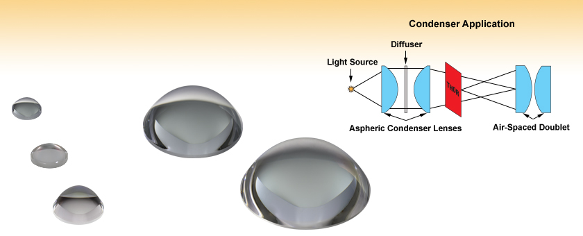
- Optimized for Illumination and Collimation
- Lens Diameters from 10 to 75 mm
- Numerical Apertures from 0.52 to 0.79
- Available Uncoated or AR-Coated for 350-700 nm or
650-1050 nm
ACL1210U
Ø12 mm, f = 10.5 mm
ACL1815U-A
Ø18 mm, f = 15 mm
ACL25416U-B
Ø1", f = 16.0 mm
ACL5040U
Ø50 mm, f = 40 mm
ACL7560U-A
Ø75 mm, f = 60 mm

Please Wait
| Table 1.1 General Specificationsa | |
|---|---|
| Design Wavelength | Visible |
| Glass Type | B270 Optical Crown Glass |
| Wavelength Range | Uncoated: 380 - 2100 nm A: 350 - 700 nmb B: 650 - 1050 nm |
| Reflectance Over AR Coating Range for Coated Optics (Avg., AOI = 0°) |
Ravg < 0.5% |
| Surface Quality | 80-50 Scratch-Dig |
| Uncoated Transmission Graph (Click Here to Download Raw Data) |
|
| A Coating Reflectance Graph (Click Here to Download Raw Data) |
|
| B Coating Reflectance Graph (Click Here to Download Raw Data) |
|
| Diameter Tolerance | +0.0 mm / -0.5 mm |
| Center Thickness Tolerance | ±0.3 mm |
| Centration | <30 arcmin |
| Maximum Temperature | 250 °C (482 °F) |
| Click on the red Document icon next to the item numbers below to access the Zemax file download. Our entire Zemax Catalog is also available. |
Click to Enlarge
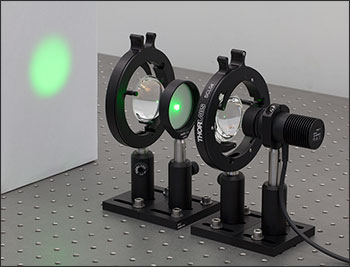
Figure 1.2 The light from an M530L4 530 nm LED is focused onto a ground glass diffuser by an ACL5040U-A aspheric condenser lens. The beam is then roughly collimated by a second ACL5040U-A lens. The square image of the LED can be seen on the surface of the diffuser. After the diffuser, the beam is uniform. Both condenser lenses are mounted in SCL04 self-centering lens mounts.
Features
- Aspheric Condenser Lenses with Larger Apertures and Higher NA than Spherical Lenses
- 13 Different Diameters From 10 to 75 mm Available
- NA from 0.52 to 0.79
- Available Uncoated or AR-Coated for 350 - 700 nm or 650 - 1050 nm
- Fabricated from B270 Optical Crown Glass (380 - 2100 nm)
High-Efficiency Illumination Applications
- Light Collection / Condensing
- Projection
- Detection
Thorlabs' Aspheric Condenser Lenses offer larger apertures, higher NA, and lower f/# ratios than spherical lenses. Therefore, these lenses are ideal for high-efficiency illumination applications or collimating light from a lamp, LED, or similar light source. Condenser lenses are not designed or recommended for forming an image on a camera sensor, which is better solved with our achromatic doublet or triplet lenses, or tube lenses.
Our condensers are sold in diameters from 10 to 75 mm and are available uncoated for 380 - 2100 nm or with an AR coating for 350 to 700 nm (-A Coating) or 650 to 1050 nm (-B Coating). The -A Coating will not completely counteract the substrate's absorptive properties from 350 nm to 380 nm. The reflectance curves for the coated versions can be found by clicking on the graph icons in Table 1.1.
Because of the shorter focal lengths and a lower f/# than other lenses, condenser lenses can be used in close proximity to one another or other optical elements, which makes them ideal for focusing light onto a detector or other light collection element. The lens surface is precision molded on the aspheric side while the plano or spherical convex side is ground and polished. For best performance, the flatter side of the lens should face the source. Please note that although the B270 substrate transmits from 380 - 2100 nm, these lenses are designed for use at visible wavelengths; focal shift plots are provided in the tables below for each lens for performance at other wavelengths.
Thorlabs offers extra-thick retaining rings with SM05 (0.535"-40), SM1 (1.035"-40), and SM2 (2.035"-40) threading that provide extra clearance for spanner wrenches when mounting these lenses (see the Lens Mounting Guide tab for more information).
For more demanding applications, we recommend our CNC-Polished, Precision Aspheres (available with N-BK7, S-LAH64, or UV Fused Silica substrates), which offer diffraction-limited performance at their design wavelength. Thorlabs also offers aspheric condensers with a polished diffuser surface on the plano side. To learn more about what type of lens is best for your application, see our Lens Tutorial page.
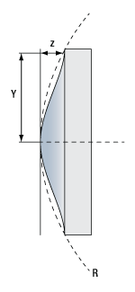
Aspheric Lens Design Formula
| Definitions of Variables | |
|---|---|
| z | Sag (Surface Profile) as a Function of Y |
| Y | Radial Distance from Optical Axis |
| R | Radius of Curvature |
| k | Conic Constant |
| An | nth Order Aspheric Coefficient |
The aspheric surface of these lenses may be described using a polynomial expansion in Y, the radial distance from the optical axis. The surface profile or sagitta (often abbreviated as sag) is denoted by z, and is given by the following expression:

where R is the radius of curvature, k is the conic constant, and the An are the nth order aspheric coefficients. The sign of R is determined by whether the center of curvature for the lens surface is located to the right or left of the lens' vertex; a positive R indicates that the center of curvature is located to the right of the vertex, while a negative R indicates that the center of curvature is located to the left of the vertex. For example, the radius of curvature for the left surface of a biconvex lens would be specified as positive, while the radius of curvature for its right surface would be specified as negative.
Aspheric Lens Coefficients
Due to the rotational symmetry of the lens surface, only even powers of Y are contained in the polynomial expansion above. The target values of the aspheric coefficients for each product can be found in Table 2.2 or by clicking on the red documents icon (![]() ) next to each lens sold below.
) next to each lens sold below.
| Table 2.2 Aspheric Lens Coefficients | |||||||||||||
|---|---|---|---|---|---|---|---|---|---|---|---|---|---|
| Item # Prefixa |
ACL108U | ACL1210U | ACL12708U | ACL1512U | ACL1815U | ACL2018U | ACL2520U | ACL25416U | ACL3026U | ACL4532U | ACL5040U | ACL50832U | ACL7560U |
| S1: R (mm) | 4.185 | 5.492 | 4.753124 | 6.277 | 7.818 | 9.415 | 10.462 | 8.818197 | 13.551 | 18.281 | 20.923 | 18.32253 | 31.384 |
| k | -0.6027 | -0.6230 | -1.205071 | -0.6139 | -1.817 | -0.6392 | -0.6265 | -0.9991715 | -0.6301 | -1.0 | -0.6405 | -0.7980728 | -1.911 |
| A4 | 2.21E-4 | 8.7E-5 | 5.3324183E-4 | 6.8E-5 | -2.93E-4 | 1.7E-5 | 1.5E-5 | 8.6821674E-5 | 5.5E-6 | 2.0E-6 | 2.0E-6 | 3.4036234E-6 | 5.0E-6 |
| A6 | 0 | 0 | 1.1162887E-5 | 0 | 0 | 0 | 0 | 6.3760123E-8 | 0 | 0 | 0 | 6.8362712E-9 | 0 |
| A8 | 0 | 0 | -3.7455666E-7 | 0 | 0 | 0 | 0 | 2.4073084E-9 | 0 | 0 | 0 | -1.9656086E-11 | 0 |
| A10 | 0 | 0 | -7.6342017E-9 | 0 | 0 | 0 | 0 | -1.7189021E-11 | 0 | 0 | 0 | 0 | 0 |
| A12 | 0 | 0 | 1.36022E-10 | 0 | 0 | 0 | 0 | 0 | 0 | 0 | 0 | 0 | 0 |
| S2b: R (mm) |
Plano | Plano | -15.6494 | Plano | Plano | Plano | Plano | -69.99948 | Plano | 130 | Plano | -99.63679 | Plano |
Video 69A Mounting Standard and High-Curvature Optics in Lens Tubes
Thorlabs' retaining rings are used to secure unmounted optics within lens tubes or optic mounts. These rings are secured in position using a compatible spanner wrench. For flat or low-curvature optics, standard retaining rings manufactured from anodized aluminum are available from Ø5 mm to Ø4". For high-curvature optics, extra-thick retaining rings are available in Ø1/2", Ø1", and Ø2" sizes.
Extra-thick retaining rings offer several features that aid in mounting high-curvature optics such as aspheric lenses, short-focal-length plano-convex lenses, and condenser lenses. As seen in Video 69A, the guide flange of the spanner wrench will collide with the surface of high-curvature lenses when using a standard retaining ring, potentially scratching the optic. This contact also creates a gap between the spanner wrench and retaining ring, preventing the ring from tightening correctly. Extra-thick retaining rings provide the necessary clearance for the spanner wrench to secure the lens without coming into contact with the optic surface.
For useful calculations when working with lenses, please click on the Lens Parameter Calculator button to download a macro-enabled Excel file. It is recommended to download and open the file in the Excel desktop application, as some features are not supported in the web version of Excel. The file includes calculations for the following parameters:
- Diffraction-Limited Spot Diameter
- Full Divergence Angle
- Maximum Waist Distance
- Beam Diameter at a Certain Distance Away
- f-Number
- Optical Invariant
Please note that macros must be enabled to use the Excel file. To enable macros, click the "Enable Content" button in the yellow message bar upon opening the file.
| Posted Comments: | |
Jaeheon Seol
(posted 2024-08-09 17:26:35.59) Hello. I sent you an email because there was something in the product description that I did not understand. The product description says that for best performance, the flat side of the lens should be in contact with the source. I am curious as to why that is, and would it be okay if I politely asked why? cdolbashian
(posted 2024-08-14 12:48:17.0) In high-efficiency illumination application, the light source is usually a point source which produces spherical wave and we want to transform it into a plane wave for illumination. It needs spread the bending of the rays over more surfaces. When the flat side of the lens is in contact with the source, it can split the ray bending most evenly and minimize the introduction of spherical aberration. A best plane wave can be achieved in this way. Jaeheon Seol
(posted 2024-05-01 14:04:00.283) Hello.
I would like to contact you because I have some questions about Aspheric lenses.
About4th, 6th, 8th... order aspheric coefficient
Some lenses only have the 4th, while others have everything from the 4th to the 12th.
I'm curious what the difference is.
Also, I understand that in the case of Aspheric lenses, the calculation of focal length follows the lens maker's formula. Is this correct?
Thank you :) cdolbashian
(posted 2024-05-10 03:41:41.0) Thanks for contacting Thorlabs! In our catalog of aspheric condenser lenses, most of the lenses with high order aspheric coefficients have a curved second surface, which contains more spherical aberration. So higher orders are used to optimize the whole lens. On the other hand, we usually control the coefficient order as low as possible from the perspective of production and quality control.
The lens maker's formula is only valid if the surfaces of the lens are spherical. Using the lens maker's formula to calculate the focal length of aspheric lenses will lead to inaccuracy. user
(posted 2023-03-15 17:26:52.647) What is the maximum power density of B270 that can be supported? Can a laser with a wavelength of 900-1000nm and a power density of 4000KW/cm² be used? cdolbashian
(posted 2023-04-03 02:11:03.0) Thank you for contacting Thorlabs! We'll reach out to you via email for some recommendations depending on your specific laser parameters. Ernest Lee
(posted 2022-12-07 06:02:13.117) We are looking into using this part in a production instrument. I'm looking for manufacturing tolerances (dimensional and aspheric shape). Thanks. jdelia
(posted 2025-11-06 09:00:15.0) Thank you for contacting Thorlabs. You should be able to receive certain dimensional tolerances for a specific part through a discussion with your local tech support team. In your case, you can reach them by emailing techsupport@thorlabs.com. Hengyi Zhou
(posted 2022-11-17 12:34:39.783) Hello sir/madam, I'm seeking professional advise on my optical design. I'm planning to use the aspheric lens (almost the largest N.A. to make the best use of light, phi = 1'', f = 16.0 mm) to collimate a green-color LED (516-540 nm), whose N.A. is close to unity. After that, a plano-convex lens will be used to focus this collimated light into the input of an optical fiber, and the output will be for other illumination use. In my understanding, to reduce the light loss inside the fiber, the angle of input light beam should not be large, i.e. the N.A. of this plano-convex lens should not be too large, so maybe a lens with phi = 1'', f = 100.0 mm will be ok? I'm not majored in optics, so I wonder if there's any unexpected issue in this design. I appreciate for your kind advise! cdolbashian
(posted 2022-11-22 04:06:25.0) Thank you for contacting Thorlabs. In this specific case, it can be seen as building a 4F system where the LED emitting area is the object, and focused beam is the image. For optimal coupling, typically the focused image size and focused beam NA need to be smaller than the fiber core diameter and NA, respectively. Due to the large emitting area of LEDs, it is not easy to focus the beam to a small enough size while meeting the NA requirements of the fiber. There is a trade-off between focusing lens NA and the focused beam diameter. It's hard to comment on this without knowing the fiber specs and light source specs. We will contact you directly to discuss your application in detail. 新莲 苗
(posted 2022-09-26 06:01:50.553) 聚焦镜反过来可以当准直镜用吗? cdolbashian
(posted 2022-10-04 04:01:10.0) Thank you for contacting Thorlabs. The Aspheric Condenser Lenses offer larger apertures, higher NA, and lower f/# ratios than spherical lenses. Therefore, these lenses are ideal for high-efficiency illumination applications or collimating light from a lamp, LED, or similar light source.
感谢您的留言。与球面透镜相比,非球面聚光透镜具有更大的孔径、更高的NA和更低的f/#比值。因此,这些非球面聚光透镜非常适合准直宽带光源、LED、或其它相似光源 amy ma
(posted 2021-07-15 20:03:37.997) ACL2520U-A is ar-coated lens, could you tell me how to clean it if there is skin oils on it? May I use isopropanol with lens tissue to clean it? Or should I use other chemical to clean it? thank you YLohia
(posted 2021-07-21 03:31:47.0) Thank you for contacting Thorlabs. Yes, you can use isopropanol with a lens tissue to clean it. You may also use methanol or acetone. First, blow off as much dust and loose contaminants as possible using an air duster. Then, apply a couple of drops of Isopropanol to a lens tissue. Using a continuous, slow and circular motion, gently remove fingerprints or skin oils outward from the lens surface. For detailed cleaning procedures, you may refer to this link: https://www.thorlabs.com/newgrouppage9.cfm?objectgroup_id=9025 qiang li
(posted 2021-06-08 17:28:58.137) hello,
I want to know why the price of Aspheric lens(material is B270)is much chiper than the CNC Aspheric lens?
And if I want to customize the lens of B270, what is the price. YLohia
(posted 2021-06-09 02:10:19.0) Hello, there is a difference in the price due to the processing technology used for molded aspheres vs CNC polished aspheres. The molded aspheres, as the name implies, employ a molding process, while the CNC polishing process is more complicated. Unfortunately, we cannot customize the molded aspheres since redesigning the mold is quite expensive and is only suitable for extremely high volume production runs. B270 is not supported using the CNC machining process due to the high risk of cracking. Hsiu Ting Wu
(posted 2020-04-30 02:56:38.7) ACL12708U-B - Aspheric Condenser Lens
Dear
Does this product have parameters of damage threshold ? YLohia
(posted 2020-04-30 10:01:24.0) Hello, thank you for contacting Thorlabs. We have not established damage threshold for these yet but we may have some recommendations depending on your laser characteristics. We will follow-up with you. roy.shiloh
(posted 2018-06-22 17:45:45.993) Like the comment of barney.william, I'm trying to calculate the NA of these lenses, albeit by a different approach, which I believe should be accurate (at least for the plano-aspherical lenses):
I take the sag formula: z=z(y), differentiate it by y: tan(alpha)=dz/dy, and then I expect to calculate: NA=sin(alpha).
I plugged in the numbers you provide in your product table. Why don't I get the NA you present? YLohia
(posted 2018-06-26 09:24:37.0) Hello, thank you for contacting Thorlabs. Is there a particular lens you are looking at that yields a significantly different NA? In general, the equations provided by Tyler (tfrisch) in response to the comment by barney.william you mentioned (NA=D/(2f) or tan(NA)=D/(2f)) are fairly decent approximations. That being said, as Tyler said in his reply, these equations will not give you the most accurate NA due to the thickness of the lens, index of refraction, etc. All of the NAs listed on this page are simulated using the ray tracing software Zemax. msamadi.52
(posted 2017-05-09 14:33:25.393) Do you have the item ACL25416U-A with standard metric size (25 mm instead of 25.4 mm)?
If not, what is your suggestion for mounting the lens? nbayconich
(posted 2017-05-18 02:23:49.0) Thank you for contacting Thorlabs. We recommend mounting our 25mm and Ø1" aspheric lenses in our SM1 threaded lens tubes prior to mounting into one of our SM1 threaded optical mounts. For example the ACL25416U-A can be mounted inside an SM1L05 and then mounted to an LMR1 fixed lens mount using our extra thick SM1RRC retaining rings.
A techsupport representative will contact you directly for more information on quoting a Ø25mm version of the ACL25416U-A. barney.william
(posted 2016-12-08 13:09:24.353) What is the formula for calculating numerical aperture?
I am using sin(atan(CA/2f)) where CA is clear aperture and f is the back focal length. That doesn't seem to give the same values listed on this page.
Thanks in advance for the education!
Bill tfrisch
(posted 2016-12-15 01:35:10.0) Hello, thank you for contacting Thorlabs. The short answer for why the NA does not match the usual models of NA=D/(2f) or tan(NA)=D/(2f) is that these condenser lenses are thick. By default modeling software often uses a paraxial ray trace, but in this case, a real ray trace is required for the most complete description of the NA. I will reach out to you with more details, but if you have access to Zemax, you can set a real ray trace using our provided models. catalinavonb
(posted 2016-02-22 09:47:17.11) Which mounting shoud be suitable for the ACL7560U condenser lens? thanks in advance for your answer! besembeson
(posted 2016-03-04 01:43:10.0) Response from Bweh at Thorlabs USA: You may consider the SCL04. Other options can be found at the following page depending on your application configuration. http://www.thorlabs.com/newgrouppage9.cfm?objectgroup_id=1488 carlos.jarrosanabria
(posted 2015-10-28 10:53:08.64) What is the power rating for these lenses? besembeson
(posted 2015-10-29 02:05:01.0) Response from Bweh at Thorlabs USA: We have not established damage threshold for these yet but have some recommendations depending on your laser characteristics. I will follow-up with you. user
(posted 2015-07-06 16:53:36.39) My question is about the back focal length on the ACL25416U (and actually other lenses for which the face other than aspherical is non-plano). I am a bit confused because on the CAD drawing the BFL is noted with "(ref)" and on that same autoCAD pdf, "ref" refers to the edge thickness. So, is the back focal length (noted fb on your reference drawing) taken from the surface S2 (from the auto CAD drawing) or from the intersection of that surface S2 with the edge (edge thickness "te")? besembeson
(posted 2015-09-22 09:46:44.0) Response from Bweh at Thorlabs USA: The back focal plane reference will be from the S2 surface. A better reference drawing for this will be here: http://www.thorlabs.com/newgrouppage9.cfm?objectgroup_id=4847 user
(posted 2014-07-18 11:08:32.2) Which is the correct BFL of the ACL3026 lens? In the datasheet it is 19.3mm, but in the ZEMAX file it is 22.6mm. myanakas
(posted 2014-08-07 08:48:37.0) Response from Mike at Thorlabs: Thank you for your feedback. The back-focal length depends on the wavelength. Also in order to determine the correct value you should apply the “Marginal Ray Height” function. This is an optimization for calculating this distance correctly. You would just have to choose it from the pull down menu in the Thickness column. So instead of “V” for Variable please choose “M”. Then this distance is calculated correctly. It is about 19mm, depending on the wavelength. If you like to change the wavelength you can also do that by going into the “WAV” menu on the upper menu of the Zemax window. jp
(posted 2014-05-27 10:36:08.48) Is the focus length of a lens is wavelength dependent? If it is ,how is the relationship between them? cdaly
(posted 2014-05-29 04:20:50.0) Response from Chris at Thorlabs: Yes, the focal length is going to be dependent on the wavelength for any lens. For the ACL108, the shift should not be any more than 0.55mm over the full range(380-2100), but I will send you the curve generated from Zemax with more detailed information. user
(posted 2014-03-25 13:37:47.407) There seems to be an error with the prescription data and .zmx file for ACL3026- its modeled performance seems to be far less than other lenses in this category. Is the prescription data for ACL3026 accurate? jlow
(posted 2014-03-27 11:44:08.0) Response from Jeremy at Thorlabs: The prescription is accurate. The ACL line is not a high performance line and are mainly used for less-demanding application. I would recommend our precision CNC-polished aspheres if you require better performance. james.parker
(posted 2014-02-04 14:10:19.02) Are the zemax files available for the new ACLxxxxxU series of aspheric condenser lenses with the spherical second surface please?
Is there a particular design intent or application for these lenses over the regular ACL series? Thank you. jlow
(posted 2014-02-27 02:21:57.0) Response from Jeremy at Thorlabs: We have made the Zemax file available for download following your feedback. jlow
(posted 2012-08-02 13:01:00.0) Response from Jeremy at Thorlabs: Using our M365L2 LED, the divergence would be about 2-3° or so (full angle). Andreas.Buck
(posted 2012-07-31 03:34:24.0) What degree of collimation is achieveable with the ACL5040? How big is the divergence using an LED like M365? tcohen
(posted 2012-02-22 13:12:00.0) Response from Tim at Thorlabs to kmurphy: Thank you for contacting us. I have emailed you the Zemax file. If you need any more information, please feel free to contact us. kmurphy
(posted 2012-02-22 11:22:04.0) I would also like the zemax files for these lenses, specifically for ACL1512. Thank you user
(posted 2011-11-30 07:35:33.0) A response from Tyler at Thorlabs: We will email you the zemax file immeadiately. Please let us know if you have any other needs. mvirgen
(posted 2011-11-29 13:27:04.0) I was wondering if i can get the zemax model for this. I have checked and updated the zemax catalog (from your website) and its not included. Thank you. sharrell
(posted 2011-09-29 08:44:00.0) A Response from Sean at Thorlabs to Andrew: Thank you for your feedback. We have added the B270 transmission curve, as well as a link to download the transmission data in an Excel spreadsheet. This may be found on the Graphs tab. alee
(posted 2011-09-29 11:44:28.0) could you put up the the transmission curves for these please, is the A coating suitable for use with one of your 385nm LED's? the A coating graph suggests it is but the substrate transmision is stated at 380, which sounds a little close to the edge.
regards
Andrew jjurado
(posted 2011-08-31 17:43:00.0) Response from Javier at Thorlabs to john.a.smith: The 4th order coefficient of the ACL2520 specified in the drawing is +1.5E-5. This information also agrees with the zmx model for this lens. I will contact you directly for further support. john.a.smith
(posted 2011-08-29 18:34:21.0) Specifications and coefficients for this aspheric lens dont seem consistent according to Zemax. Is the 4th order coefficient for the ACL2520 equal to -1.5e-5, not +1.5e-5?
Thanks!
John Thorlabs
(posted 2010-12-01 15:42:32.0) Response from Javier at Thorlabs to Edgar: I will work with our web team on updating this page with ZEMAX files for the aspheric condenser lenses. In the meantime, I will send you the zmx file for the ACL2520. edgar.guevara
(posted 2010-11-30 18:09:24.0) Can you post the full prescription data for ZEMAX, I think it would be very useful for all the users. I am trying to collimate the light from a LED, but I do not know if this aspheric (ACL2520) is enough. Thorlabs
(posted 2010-10-11 14:06:22.0) Response from Javier at Thorlabs to saxena.a: We would recommnend using the AL2520-A large diameter aspheric lens for this purpose. This lens, designed for diffraction-limited performance, has a better collection efficiency and better resolution than its ACL counterpart. Thorlabs
(posted 2010-07-07 08:28:15.0) Response from Javier at Thorlabs to mrubioroy: thank you for your reply. The easiest way to determine where the principal planes are for this lens is by ray tracing. For this purpose, it is important to know the wavelength(s) that you are working at, since Snells law needs to be applied, and we would need to know the index of refraction of the lens material at the operating wavelength. Also, beam diameter needs to be considered. I will contact you directly to work out all these details. mrubioroy
(posted 2010-06-09 12:22:40.0) Response to Javier: I guess my question should be: Can I know where the principal planes are? Javier
(posted 2010-06-08 04:24:57.0) Response from Javier at Thorlabs to mrubio: for a thin lens, the effective focal length can be considered as being measured from the center of the lens to the focal point. However, for a thick lens such as the ACL2520, the focal length is measured from one of the pricipal planes, which are basically defined as hypothetical planes were all the refraction is considered to happen. The thin lens equation can be used, but it disregards the distance between these planes. Gullstrands equation takes this distance into account, but the calculation process can get very involved. So, although the answer is not straightforward, you can consider the effective focal length as being measured a few millimiters from the convex surface of the lens. I will contact you directly in case you would like to discuss this further. Regarding your question about back focal length, you are correct; it is measured from the flat, or plano, side. mrubio
(posted 2010-06-07 16:20:13.0) From where is the EFL of 20mm on ACL2520 measured? Is the back focal distance measured from the flat side? apalmentieri
(posted 2009-11-02 08:15:02.0) A response from Adam at Thorlabs: I will send you all of the aspheric lens data that you will need. dinesharakere
(posted 2009-11-02 03:36:18.0) Sir,
We had optimized our setup using AL108 and AL1210 combination for a Fluorescence detection (non-imaging application) setup. During websearch can find ACL108 and ACL 1210, which are much cheaper.
Can I please have the aspheric lens prescription data - so that I can verify in Zemax that whether the alternate and cheaper substitute can meet the previous design performance. klee
(posted 2009-10-12 14:08:37.0) A response from Ken at Thorlabs: You are correct that the flat side should be facing the focus and the curved side should be facing collimation. We will correct this shortly. thorlabs
(posted 2009-10-09 21:28:01.0) Is the setup shown here correct?
The Aspheric Condenser Lenses page shows two condenser lenses with curved faces toward each other. As I look at your picture, I see collimated light to the left and to the right of the pair (external to the pair) and light focused to a point between the pair. Normally the flat side of the lens faces toward focus and the curved side faces toward collimation. apalmentieri
(posted 2009-08-14 16:15:04.0) A response from Adam at Thorlabs: I understand your concerns and will send you all of the prescription information we currently can provide. I will also speak with our technical marketing department about adding this information to our website. erik.foerster
(posted 2009-08-14 04:15:33.0) For an optic designer it is imported to know the full description of the optical surfaces. Otherwise this product-information is really void. |

| Item # | Diameter (mm) |
Focal Length (mm)a |
Focal Shift (Raw Data) |
f/#b | Clear Aperture (mm) |
Back Focal Length (mm) |
Numerical Aperturec |
Center Thickness (mm) |
Edge Thickness (mm) |
Non-Aspheric Surface |
Suggested Lens Mounts |
Reference Drawing |
|---|---|---|---|---|---|---|---|---|---|---|---|---|
| ACL108U | 10.0 | 8.0 | 0.89 | >9.0 | 4 | 0.61 | 5.8 | 2.1 | Plano | LMR10(/M) | ||
| ACL1210U | 12.0 | 10.5 | 0.97 | >10.8 | 7 | 0.54 | 5.8 | 1.9 | Plano | LH1(/M) | ||
| ACL12708U | 12.7 | 8.0 | 0.70 | >11.4 | 3.7 | 0.78 | 7.5 | 1.6 | Spherical Convex | LMR05(/M) | ||
| ACL1512U | 15.0 | 12.0 | 0.89 | >13.5 | 7 | 0.61 | 8.0 | 2.4 | Plano | LMR15(/M) | ||
| ACL1815U | 18.0 | 15.0 | 0.93 | >16.2 | 10 | 0.57 | 8.2 | 2.0 | Plano | LMR18(/M) | ||
| ACL2018U | 20.0 | 18.1 | 1.01 | >18.0 | 13 | 0.52 | 8.0 | 1.8 | Plano | LMR20(/M) | ||
| ACL2520U | 25.0 | 20.1 | 0.89 | >22.5 | 12 | 0.60 | 12.0 | 2.8 | Plano | LH1(/M) | ||
| ACL25416U | 25.4 | 16.0 | 0.70 | >22.9 | 7.3 | 0.79 | 14.0 | 1.2 | Spherical Convex | LMR1(/M) | ||
| ACL3026U | 30.0 | 26.0 | 0.96 | >27.0 | 18 | 0.55 | 11.9 | 2.1 | Plano | LMR30(/M) | ||
| ACL4532U | 45.0 | 32.1 | 0.79 | >40.5 | 21 | 0.60 | 18.5 | 2.2 | Spherical Convex | LMR45(/M) | ||
| ACL5040U | 50.0 | 40.0 | 0.89 | >45.0 | 26 | 0.60 | 21.0 | 2.6 | Plano | LH2(/M) | ||
| ACL50832U | 50.8 | 32.0 | 0.70 | >45.7 | 17 | 0.76 | 25.0 | 1.9 | Spherical Convex | LMR2(/M) | ||
| ACL7560U | 75.0 | 60.0 | 0.89 | >67.5 | 40 | 0.61 | 30.0 | 2.3 | Plano | LMR75(/M) |

| Item # | Diameter (mm) |
Focal Length (mm)a |
Focal Shift (Raw Data) |
f/#b | Clear Aperture (mm) |
Back Focal Length (mm) |
Numerical Aperturec |
Center Thickness (mm) |
Edge Thickness (mm) |
Non-Aspheric Surface |
Suggested Lens Mounts |
AR Coating | Reference Drawing |
|---|---|---|---|---|---|---|---|---|---|---|---|---|---|
| ACL108U-A | 10.0 | 8.0 | 0.89 | >9.0 | 4 | 0.61 | 5.8 | 2.1 | Plano | LMR10(/M) | 350 - 700 nm (Ravg < 0.5%) | ||
| ACL1210U-A | 12.0 | 10.5 | 0.97 | >10.8 | 7 | 0.54 | 5.8 | 1.9 | Plano | LH1(/M) | |||
| ACL12708U-A | 12.7 | 8.0 | 0.70 | >11.4 | 3.7 | 0.78 | 7.5 | 1.6 | Spherical Convex | LMR05(/M) | |||
| ACL1512U-A | 15.0 | 12.0 | 0.89 | >13.5 | 7 | 0.61 | 8.0 | 2.4 | Plano | LMR15(/M) | |||
| ACL1815U-A | 18.0 | 15.0 | 0.93 | >16.2 | 10 | 0.57 | 8.2 | 2.0 | Plano | LMR18(/M) | |||
| ACL2018U-A | 20.0 | 18.1 | 1.01 | >18.0 | 13 | 0.52 | 8.0 | 1.8 | Plano | LMR20(/M) | |||
| ACL2520U-A | 25.0 | 20.1 | 0.89 | >22.5 | 12 | 0.60 | 12.0 | 2.8 | Plano | LH1(/M) | |||
| ACL25416U-A | 25.4 | 16.0 | 0.70 | >22.9 | 7.3 | 0.79 | 14.0 | 1.2 | Spherical Convex | LMR1(/M) | |||
| ACL3026U-A | 30.0 | 26.0 | 0.96 | >27.0 | 18 | 0.55 | 11.9 | 2.1 | Plano | LMR30(/M) | |||
| ACL4532U-A | 45.0 | 32.1 | 0.79 | >40.5 | 21 | 0.60 | 18.5 | 2.2 | Spherical Convex | LMR45(/M) | |||
| ACL5040U-A | 50.0 | 40.0 | 0.89 | >45.0 | 26 | 0.60 | 21.0 | 2.6 | Plano | LH2(/M) | |||
| ACL50832U-A | 50.8 | 32.0 | 0.70 | >45.7 | 17 | 0.76 | 25.0 | 1.9 | Spherical Convex | LMR2(/M) | |||
| ACL7560U-A | 75.0 | 60.0 | 0.89 | >67.5 | 40 | 0.61 | 30.0 | 2.3 | Plano | LMR75(/M) |

| Item # | Diameter (mm) |
Focal Length (mm)a |
Focal Shift (Raw Data) |
f/#b | Clear Aperture (mm) |
Back Focal Length (mm) |
Numerical Aperturec |
Center Thickness (mm) |
Edge Thickness (mm) |
Non-Aspheric Surface |
Suggested Lens Mounts |
AR Coating |
Reference Drawing |
|---|---|---|---|---|---|---|---|---|---|---|---|---|---|
| ACL108U-B | 10.0 | 8.0 | 0.89 | >9.0 | 4 | 0.61 | 5.8 | 2.1 | Plano | LMR10(/M) | 650 - 1050 nm (Ravg < 0.5%) |
||
| ACL1210U-B | 12.0 | 10.5 | 0.97 | >10.8 | 7 | 0.54 | 5.8 | 1.9 | Plano | LH1(/M) | |||
| ACL12708U-B | 12.7 | 8.0 | 0.70 | >11.4 | 3.7 | 0.78 | 7.5 | 1.6 | Spherical Convex | LMR05(/M) | |||
| ACL1512U-B | 15.0 | 12.0 | 0.89 | >13.5 | 7 | 0.61 | 8.0 | 2.4 | Plano | LMR15(/M) | |||
| ACL1815U-B | 18.0 | 15.0 | 0.93 | >16.2 | 10 | 0.57 | 8.2 | 2.0 | Plano | LMR18(/M) | |||
| ACL2018U-B | 20.0 | 18.1 | 1.01 | >18.0 | 13 | 0.52 | 8.0 | 1.8 | Plano | LMR20(/M) | |||
| ACL2520U-B | 25.0 | 20.1 | 0.89 | >22.5 | 12 | 0.60 | 12.0 | 2.8 | Plano | LH1(/M) | |||
| ACL25416U-B | 25.4 | 16.0 | 0.70 | >22.9 | 7.3 | 0.79 | 14.0 | 1.2 | Spherical Convex | LMR1(/M) | |||
| ACL3026U-B | 30.0 | 26.0 | 0.96 | >27.0 | 18 | 0.55 | 11.9 | 2.1 | Plano | LMR30(/M) | |||
| ACL4532U-B | 45.0 | 32.1 | 0.79 | >40.5 | 21 | 0.60 | 18.5 | 2.2 | Spherical Convex | LMR45(/M) | |||
| ACL5040U-B | 50.0 | 40.0 | 0.89 | >45.0 | 26 | 0.60 | 21.0 | 2.6 | Plano | LH2(/M) | |||
| ACL50832U-B | 50.8 | 32.0 | 0.70 | >45.7 | 17 | 0.76 | 25.0 | 1.9 | Spherical Convex | LMR2(/M) | |||
| ACL7560U-B | 75.0 | 60.0 | 0.89 | >67.5 | 40 | 0.61 | 30.0 | 2.3 | Plano | LMR75(/M) |
 Products Home




 Aspheric Condenser Lenses