Ultrafast Broadband Beamsplitters with Controlled Dispersion

- Deterministic GDD for Femtosecond Laser Pulses
- Designed for P-Polarized Light at 45° AOI
- Infrasil® Windows Available to Balance GDD
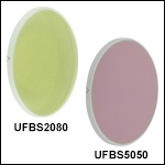
UFBS2080
20:80 Ultrafast Beamsplitter
(600-1500 nm)
UFBS8020
80:20 Ultrafast Beamsplitter
(600 - 1500 nm)
Application Idea
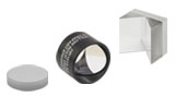
UFBS5050 50:50 Ultrafast Beamsplitter in a
UFBS9010
90:10 Ultrafast Beamsplitter
(600 - 1500 nm)
UFBS50502
50:50 Ultrafast Beamsplitter
(1000 - 2000 nm)

Please Wait
Features
- Deterministic Group Delay Dispersion (GDD) in Reflection and Transmission
- Designed for P-Polarized Light Incident at 45°
- Split Ratios:
- 20:80, 50:50, 80:20, or 90:10 (R:T) for 600 - 1500 nm
- 50:50 for 1000 - 2000 nm
- Optimized for Femtosecond Ti:Sapphire and Yb Lasers
- 1.0 mm Thick Infrasil Windows to Balance UFBS5050 GDD
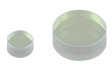
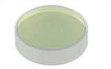
Thorlabs' Ultrafast Broadband Beamsplitters offer a 20:80, 50:50, 80:20, or 90:10 (R:T) beamsplitting ratio over the 600 - 1500 nm wavelength range, or a 50:50 (R:T) beamsplitting ratio over the 1000 - 2000 nm wavelength range. They are designed to be used with p-polarized light incident at 45° and are not intended to be used for s-polarized light. For s-polarized or circularly polarized light applications, please see our full selection of plate beamsplitters. As shown by the images at the top of the page, each ultrafast beamsplitter is marked with an arrow that points toward the beamsplitting coating; light being split should be incident on this surface to obtain the intended performance. The wide usable wavelength range of these beamsplitters makes them compatible with femtosecond pulsed Ti:Sapphire, Yb, and Er fiber lasers. The beamsplitters have an AR coating on the back surface that provides <0.5% absolute reflectance over the same wavelength range as the beamsplitter coating. The Infrasil substrate is a type of optical quartz that has nearly identical dispersion to fused silica but higher internal transmission around 1380 nm.
Mounting Options
Our ultrafast beamsplitters and Infrasil windows are too thin for standard setscrew-based mounts. Hence, we recommend mounting them in retaining-ring-based mounts, such as our Polaris® SM1-threaded mounts or fixed optic mounts. Retaining rings apply less mechanical stress to the optic than setscrews, helping to prevent bending of the optical surfaces, which compromises performance. The 4.0 mm thick beamsplitters can also be mounted in our Polaris Low-Distortion Optic Mounts. Alternatively, the beamsplitters can be installed in a POLARIS-K1C4 glue-in kinematic mirror mount or a POLARIS-B1G glue-in fixed mount. The POLARIS-B1G features two cut-outs to maximize the transmissive clear aperture at 45° AOI, making it an ideal mount for a plate beamsplitter.
Balancing GDD in the Transmitted and Reflected Beam
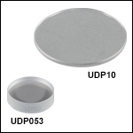
When using the UFBS5050 ultrafast beamsplitter with pulses shorter than 50 fs, we recommend inserting one of our 1.0 mm thick Infrasil windows into the reflected beam at a 0° angle of incidence in order to balance the GDD. We offer 1.0 mm thick Infrasil windows in Ø1/2" (Item # UDP05) and Ø1" (Item # UDP10) sizes. The uncoated windows have flat transmission from 300 nm to 3 µm, as shown in the table below. Using one of these 1.0 mm thick windows reduces the GDD difference between the transmitted and reflected arms to <20 fs2 at 800 nm. Longer pulses have a narrow spectral bandwidth that negates the need for additional dispersion compensation. See the Group Delay tab for additional details. For our other ultrafast beamsplitters, our 1.0 mm thick Infrasil windows are not thick enough to balance the dispersion exactly, but they will still improve dispersion matching between the beams. When using our 4.0 mm thick beamsplitters, the 3.0 mm and 5.0 mm thick Infrasil window (Item #s UDP053 and UDP105) may be used to provide some dispersion compensation, although it was not specifically designed to match those items. Alternatively, one of our uncoated UV fused silica windows may be used.
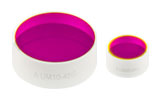
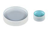
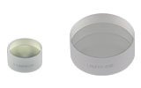
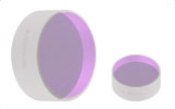
Thorlabs' selection of ultrafast optics also includes low-GDD mirrors for 700 - 930 nm, 950 - 1170 nm, 1400 - 1700 nm, and 1760 - 2250 nm. For our full selection, please see the Ultrafast Optics tab.
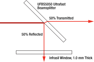
Recommended Configuration for Balanced Dispersion in Transmitted and Reflected Beams of 50:50 Ultrafast Beamsplitter (Only Necessary for
| Item # | GDD in Reflection |
|---|---|
| UFBS2080 | 0.2 mm of Fused Silica |
| UFBS5050 | 0.7 mm of Fused Silica |
| UFBS8020 | 2 mm of Fused Silica |
| UFBS9010 | |GDD| < 150 fs2 (See Note a) |
| UFBS50502 | 0.7 mm of Fused Silica |
Balanced Group Delay for 50:50 Ultrafast Beamsplitter
The UFBS5050 Ultrafast Beamsplitter provides a 50:50 beamsplitting ratio for femtosecond laser pulses with well-defined, nearly equal group delay dispersion in the transmitted and reflected beams. For the shortest pulses (<50 fs), additional dispersion compensation is recommended, as detailed in the text below. Please note for the following discussion that Infrasil® and fused silica have nearly identical dispersion.
Transmitted Beam
When the UFBS5050 beamsplitter is oriented at a 45° incident angle, the transmitted pulse will be dispersed by traveling 1.7 mm through the Infrasil substrate (assuming the substrate is 1.5 mm thick). The plot below on the left compares the measured group delay through the UFBS5050 beamsplitter to the calculated group delay through 1.7 mm of Infrasil.
Reflected Beam
The beamsplitting coating is designed to impart on the reflected pulse the same amount of dispersion as traveling through 0.7 mm of fused silica (see the table to the right). The plot below on the right shows that the measured group delay of the reflected beam is similar to the calculated group delay through 0.7 mm of fused silica, as expected. The measurement stops at 1100 nm due to limitations of the white light interferometer used for this test.
In order to balance the dispersion of the reflected beam with that of the transmitted beam, either of our 1.0 mm thick Infrasil windows can be inserted into the reflected beam at a 0° incident angle. This geometry is shown in the figure to the right. The window allows the net dispersion of the reflected beam to be the same as traveling through 1.7 mm of Infrasil. For pulses with narrow spectral bandwidth (i.e., pulses longer than 50 fs), the group delay dispersion varies slowly enough that this additional window is not necessary.
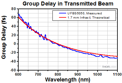
Click to Enlarge
Group Delay in Transmission
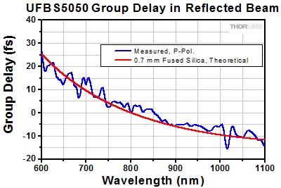
Click to Enlarge
Group Delay in Reflection
Thorlabs offers a wide selection of optics optimized for use with femtosecond and picosecond laser pulses. Please see below for more information.
| Low-GDD Mirrors | |||||
|---|---|---|---|---|---|
 |
 |
 |
 |
 |
 |
| 355 - 445 nm | 460 - 590 nm | 700 - 930 nm | 970 - 1150 nm | 1400 - 1700 nm | 1760 - 2250 nm |
| Dielectric Mirror | High-Power Mirrors for Picosecond Lasers |
Metallic Mirrors | Low-GDD Pump-Through Mirrors |
||
|---|---|---|---|---|---|
 |
 |
 |
 |
 |
 |
| Dual-Band Dielectric Mirror, 400 nm and 800 nm |
Ytterbium Laser Line Mirrors, 250 nm - 1080 nm |
Ultrafast-Enhanced Silver Mirrors, 750 - 1000 nm |
Protected Silver Mirrors, 450 nm - 20 µm |
Unprotected Gold Mirrors, 800 nm - 20 µm |
Pump-Through Mirrors, 1030 - 1080 nm and 940 - 980 nm |
| Deterministic GDD Beamsplitters |
Low-GDD Harmonic Beamsplitters |
Low-GDD Polarizing Beamsplitters |
β-BBO Crystals | Dispersion-Compensating Optics | |
|---|---|---|---|---|---|
 |
 |
 |
 |
 |
 |
| Beamsplitters & Windows, 600 - 1500 nm or 1000 - 2000 nm |
Harmonic Beamsplitters, 400 nm and 800 nm or 500 nm and 1000 nm |
High-Power, Broadband, High Extinction Ratio Polarizers, 700 - 1300 nm | β-BBO Crystals for Second Harmonic Generation |
Dispersion-Compensating Mirrors, 650 - 1050 nm |
Dispersion-Compensating Prisms, 700 - 900 nm |
| Posted Comments: | |
Marco Gaulke
(posted 2024-06-28 15:17:21.553) Dear Thorlabs team,
do you have calculated splitting ratios of this product for (the wrong) s-polarization. I would be interested in that.
Also do you have calculations or data for the angular dependence of the splitting ratio at a fixed wavelength, e.g. 1450 nm?
All the best,
Marco cdolbashian
(posted 2024-07-19 03:54:14.0) Thank you for reaching out to us with this inquiry.
The specced performance, as well as the design goals of this component are dependent on the use of P-polarized light exclusively. These are not characterized or tested with S polarized light. As this is the case, the performance would likely vary from batch-to-batch or unit-to-unit. I have contacted you directly with an example of some test data though we do not have angular dependence of these data. Georgi Yankov
(posted 2024-02-29 08:36:03.77) Hello,
Do you have (Ultrafast Beamsplitter) only 2" and in the tower do you plan to offer those.
I need 90:10, 80:20, 70:30, 60:40, 50:50. 2" in diameter. For wavelengths from 240 to 2600 nm.
Best Regards
George jdelia
(posted 2024-03-01 09:56:56.0) Thank you for contacting Thorlabs. While this is not something we currently offer, I can certainly make note of your request internally so we may look into this in the future. Georgi Yankov
(posted 2024-02-29 08:33:38.347) Hello,
Do you have (Ultrafast Beamsplitter) only 2" and in the tower do you plan to offer those.
I need 90:10, 80:20, 70:30, 60:40, 50:50. 2" in diameter. For wavelengths from 240 to 2600 nm.
Best Regards
George Eugen Nosenko
(posted 2023-11-02 15:01:25.453) How do the UFBS50502 and UFBS8020 work with s-polarized light? Can you provide the correspording reflectivity & dispersion curves? Thanks. cdolbashian
(posted 2023-11-15 03:47:51.0) Thank you for reaching out to us with this inquiry. As we explicitly designed these to work optimally with P-polarized light, we do not have data for the S-polarization. I have reached out to you directly to discuss your application, and a possible alternative. Jonas Kuhl
(posted 2020-10-29 04:53:54.72) Dear Sir or Madam, coming back to the Question asked by mastron in 2015. Is there now an option to get the UFBS9010 in a size of Ø2 or is the coating problem still present?
With kind regards,
Jonas Kuhl. YLohia
(posted 2020-10-29 10:59:50.0) Hello Jonas, we still do not offer a Ø2" version of these beamsplitters due to the same concerns. The coating would severely bend the substrate and would result in a surface flatness of >> 1λ. Xianyu Ao
(posted 2020-08-15 10:08:55.173) Dear Sir/Madam,
Could you please provide the reflection/transmissiton curve of UFBS5050 for s-polarization? BTW, how p-polarization is defined? How to intall UFBS5050, 1 inch diameter, into a 30 mm cage cube? Thanks a lot!
Best,
Xianyu YLohia
(posted 2020-08-18 09:54:27.0) Hello Xianyu, thank you for contacting Thorlabs. I have reached out to you with the s-polarization plots. P-polarized light has its electric field along the plane of incidence. This optic can be mounted into a 30 mm cage cube using the B5CT1 cage cube optic mount. Nils Lenngren
(posted 2020-02-06 12:49:53.98) Dear Sir or Madam,
We need to clean one of our UFBS5050 beamsplitters, and therefore I wonder what material is used for the antireflective coating, in order to find a solvent that will not damage the coating.
Best regards,
Nils Lenngren YLohia
(posted 2020-02-06 04:31:26.0) Hello Nils, thank you for contacting Thorlabs. Unfortunately, we cannot disclose the coating material as the information is proprietary. We would recommend cleaning with isopropyl aclohol using the methods posted here : https://www.thorlabs.com/newgrouppage9.cfm?objectgroup_id=9025 Kurtis Borne
(posted 2019-10-25 15:28:11.503) I am very interested in purchasing the 90:10 ultrafast beamsplitter.
It would be used with a 800 nm, 25 fs beam with a 2 mJ pulse energy (@ 10 kHz).
All the specs seem appropriate, but obviously with these short wavelengths I'm very susceptible to GDD, and I am confused what it means in the provided plot for "reflected GDD." I don't understand the meaning of reporting a GDD for the reflected part of the beam and not the transmitted, and I am worried that the transmitted GDD would be much larger than the acceptable ~25fs^-2 that is reported .
Please let me know if you have any information YLohia
(posted 2019-10-28 03:23:03.0) Thank you for contacting Thorlabs. The transmitted GDD of coatings is usually very small (i.e. < 10 fs^2), which is the case with the UFBS9010. So, the total transmitted GDD is just the material (Infrasil) dispersion. ikb2
(posted 2017-07-12 11:18:10.77) Considering using the beamsplitter/infrasil window combination in an interferometric setup. It seems that if the beams are retroreflected and recombined within the beamsplitter, then the two arms pick up different amounts of dispersion. The reflected beam reflects, passes twice through the infrasil window, then transmits, accumulating 4.4 mm worth of dispersion. The transmitted beam transmits through the beam splitter twice, reflects, and then transmits again, accumulating 5.8 mm worth of dispersion. Do you have a recommendation for working with this setup in the sub-100 fs regime? tfrisch
(posted 2017-09-05 10:45:13.0) Hello, thank you for contacting Thorlabs. It sounds like you are describing a Michelson configuration in which the arm which is reflected, then transmitted, has a different delay than the arm that is transmitted, then reflected. With the compensator plate, the R-R arm and T-T arm can be matched in delay, assuming the retroreflector displaces the beam by more than the beam diameter. A simpler solution might be to use a Mach-Zender configuration. I will reach out to you about this directly. tug13936
(posted 2017-06-13 12:38:56.19) Can you explain why this kind of beam splitter can not work for s-polarization? Can you send me any data for the testing with s-polarization? tfrisch
(posted 2017-06-30 02:56:00.0) Hello, thank you for contacting Thorlabs. The S-state has much worse performance because this was optimized for the P-state. I will reach out to you directly with some typical data. elharel
(posted 2016-12-18 16:51:16.62) Would it be possible to get a 80:20 version? tfrisch
(posted 2016-12-20 02:49:15.0) Hello, thank you for contacting Thorlabs. I will reach out to you directly with details on our custom coating capabilities. m.c.ashby
(posted 2015-12-04 18:17:39.387) Can this beamsplitter be used in reverse to combine two Ultrafast Ti:Sph beams? What is the dependence on polarization? besembeson
(posted 2015-12-07 10:47:21.0) Response from Bweh at Thorlabs USA: Yes you can use this in reverse direction, provided you are familiar with the issues related to phase-sensitivity when coherently combining two beams. If you are hoping to combine one S- and one P-polarized beam (and if the S-reflectivity is acceptable), then I'd suggest using the S-polarized beam in transmission because the dispersion is better behaved. Our UK division will share the S-polarized reflectivity example data with you. sunryu
(posted 2015-06-17 01:55:25.563) It would fit my application. What is the damage threshold? Is this safe for 4 W Ti:Sapphire oscillator output (140 fs, 80 MHz)? jlow
(posted 2015-07-07 10:40:16.0) Response from Jeremy at Thorlabs: We are going to be testing these in the near future and we will post the data to the web when the test is finished. mastron
(posted 2015-05-18 20:09:34.93) It would be nice if the "Low-GDD Ultrafast Beamsplitter for 600 - 1500 nm" and matched Infrasil windows came in Ø2" sizes. Also I'm not sure if I'm missing it somewhere but what is the power damage threshold for these optics? jlow
(posted 2015-07-07 10:35:54.0) Response from Jeremy at Thorlabs: We do not currently have a Ø2" version for these mirrors. The coating would severely bend the substrate and one could expect bad surface flatness so this may not be feasible for some applications. With regard to the damage threshold, we are going to be testing them in the near future and we will post the data to the web when the test is finished. |

| Item # | UFBS2080 | UFBS5050 | UFBS8020 | UFBS9010 | |
|---|---|---|---|---|---|
| Overall Performance |
Rabs = 20 ± 2% Tabs = 80 ± 2% |
Rabs = 50 ± 5% Tabs = 50 ± 5% |
Rabs = 80 ± 5% Tabs = 20 ± 5% |
Rabs = 90 ± 2% Tabs = 10 ± 2% |
|
| Wavelength Range | 600 - 1500 nm | ||||
| AR Coating | Rabs < 0.5% over 600 - 1500 nm | ||||
| Diameter | 1" (25.4 mm) | ||||
| Diameter Tolerance | +0.00/-0.10 mm | ||||
| Thickness | 1.5 mm | 4.0 mm | |||
| Thickness Tolerance | ±0.10 mm | ||||
| Clear Aperture | >80% of Diameter | ||||
| Angle of Incidence (AOI) | 45° | ||||
| Laser-Induced Damage Thresholda |
0.18 J/cm2 (800 nm, 51 fs FWHM, P-Pol, 1000 Pulses) | 0.17 J/cm2 (800 nm, 51 fs FWHM, P-Pol, 1000 Pulses) | - | - | |
| Input Polarization | P Polarization | ||||
| Surface Quality | 15-5 Scratch-Dig | 15-10 Scratch Dig | |||
| Surface Flatness | <λ/5 Over Clear Aperture | <3λ Over Clear Aperture | <1λ Over Clear Apertureb | <1λ Over Clear Aperturec | |
| Parallelism | ≤5 arcmin | ||||
| Substrate | Infrasil® | ||||
| Reflectance/Transmission | Raw Data |
Raw Data |
Raw Data |
Raw Data |
|
| Group Delay (GD) | - | Reflection Raw Data |
Transmission Raw Data |
Reflection Raw Data |
- |
| Group Delay Dispersion (GDD) | - | - | - | - | Reflection Raw Data |

| Item # | UFBS50502 | |
|---|---|---|
| Overall Performance |
Rabs = 50 ± 5% Tabs = 50 ± 5% |
|
| Wavelength Range | 1000 - 2000 nm | |
| AR Coating | Rabs < 0.5% over 1000 - 2000 nm | |
| Diameter | 1" (25.4 mm) | |
| Diameter Tolerance | +0.00/-0.10 mm | |
| Thickness | 4.0 mm | |
| Thickness Tolerance | ±0.10 mm | |
| Clear Aperture | >80% of Diameter | |
| Angle of Incidence (AOI) | 45° | |
| Laser-Induced Damage Threshold |
- | |
| Input Polarization | P Polarization | |
| Surface Quality | 15-10 Scratch-Dig | |
| Surface Flatness | <2λ Over Clear Aperturea | |
| Parallelism | ≤5 arcmin | |
| Substrate | Infrasil® | |
| Reflectance/Transmission | Raw Data |
|
| Group Delay (GD) | Reflection Raw Data |
Transmission Raw Data |


Recommended Configuration with a 1.0 mm Window
for Balanced Dispersion in Transmitted and Reflected
Beam of 50:50 Ultrafast Beamsplitter (Only Necessary
for Sub-50 fs Pulses)
Thorlabs offers both 1.0 mm, 3.0 mm, and 5.0 mm thick Infrasil windows. The 1 mm thick windows are recommended for use with the UFBS5050 ultrafast beamsplitter with pulses shorter than 50 fs. See the Group Delay tab for more details.
| Item # | UDP05 | UPD053 | UDP10 | UDP105 | |
|---|---|---|---|---|---|
| Diameter | 1/2" (12.7 mm) | 1" (25.4 mm) | |||
| Diameter Tolerance | +0.0 / -0.1 mm | +0.0 / -0.2 mm | +0.0 / -0.1 mm | +0.0 / -0.2 mm | |
| Thickness | 1.0 mm | 3.0 mm | 1.0 mm | 5.0 mm | |
| Thickness Tolerance | ±0.1 mm | ±0.3 mm | ±0.1 mm | ±0.3 mm | |
| Clear Aperture | >90% of Diameter | ≥80% of Diameter | >80% of Diameter | ≥85% of Diameter |
|
| Parallelism | <5 arcmin | <3 arcmin | <5 arcmin | <3 arcmin | |
| Transmitted Wavefront Errora |
<λ/10 Over Clear Aperture | ||||
| Surface Quality | 10-5 Scratch-Dig | ||||
| Wavelength Range | 300 nm - 3 µm (Uncoated) | ||||
| Substrate | Infrasil® | ||||
| Transmission Data | Raw Data |
Raw Data |
Raw Data |
Raw Data |
|
 Products Home



 Zoom
Zoom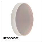
 Controlled-GDD Beamsplitters