Laser Safety Curtain System
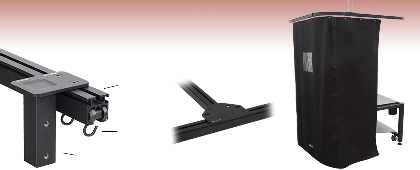
- Construct Custom Laser Safety Curtains Using Standard Parts
- Options for Wall, Floor, and Ceiling Mounting
- Modular Components Allow for Customization
Curtain Tracks Available in Seven Lengths
Wheel Runners for Mounting Curtains to the Tracks
Post for Attaching to Floor Mounting Column
Track Connectors are Used to Attach Two or More Curtain Tracks Together
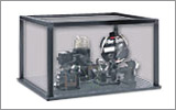
Laser Curtain System Constructed Around a ScienceDesk Workstation

Please Wait
Laser Curtain System Component Selection Process
| Step 1 Measure Space Dimensions |
Step 2 Select Tracks and Track Connectors |
Step 3 Select Laser Curtains and Valances |
Step 4 Select Floor/Wall Mounting Elements |
|||
 |
 |
 |
 |
Common Configurations
To see more configurations, please see the Example Configurations tab.
Features
- Flame Retardant Laser Curtains with Magnetic Connectors for Simple Light-Tight Seals
- Curtain Tracks and Track Connectors Create a Path for Laser Curtains to Follow
- Laser Valance Panels to Cover Gaps Near the Ceiling or Curtain Tracks
- Individual Components for Mounting System to Walls, Ceilings, and Floors Using Mounting Brackets or Floor Columns
- Hardware Kits for Mounting Valance Panels to Tracks or Rods
- Wheel Runners Allow for Quick and Easy Curtain Panel Adjustment
- Floor Mounting Brackets and Columns for Mounting the Curtain System in the Lab
- Curtain End Stops Provide a Hard Stop Along Tracks
Thorlabs' Laser Safety Curtain System provides a modular assembly that imparts the ability to fully customize a system to fit most lab spaces using a standard system of components. This system features laser curtain panels, valance panels, curtain tracks, track connectors, and floor mounting adapters that are each sold individually. The flexibility inherited from using standard components makes it easy to augment an existing Thorlabs laser curtain system or replace specific parts in it.
The laser curtain system can be used at an entrance way, as a barrier around an optical table or workstation, to cover windows, or as a barrier for any other laser-controlled area. For example system configurations with part lists, please see the Example Configurations tab above. Please note that these laser curtains are not intended to be used as long term beam blocks and are rated for short term exposures. The curtain and valance materials have been tested individually by a third party using EN specifications; see the Certifications tab above for more details. For terminating a pulsed or CW laser, see our selection of beam blocks and traps.
To begin constructing a laser safety curtain system for your lab, simply follow the steps outlined in the Component Selection Process to the right. Curtain tracks are available with seven length options to choose from, including a curved, 90° track. Various track connectors are provided to connect two, three, or four tracks together. Most track connectors also include mounting slots or additional brackets to help attach the curtain system to a wall, ceiling, or floor element. Dedicated wall, ceiling, or floor mounting adapters are also provided to secure the system in place, with mounting kits for valance panels also available. When mounting a curtain system, we recommend installing track supports for every 1 m of track for ceiling supports and every 1.2 m of track for floor supports. Please contact Thorlabs Tech Support with any questions about how to configure a system for your lab.
Due to different building codes, material types, and room designs, we do not include any hardware needed to mount the system to floors, ceilings, or walls. Please be aware of the overall weight of the mounted system and choose screws and fittings that are suitable and have enough holding strength for use in your wall or ceiling. If you are uncertain, please consult a specialized retailer.
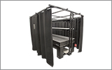
Laser Safety Curtain Kits are also available that include all components needed to mount laser curtains to a Nexus® Optical Table Workstation Frame, which has an overhead shelving unit installed, or directly to our Free-Standing Shelves. Kits that fully enclose a 1 m x 2 m, 1.2 m x 2 m, or 1.2 m x 2.5 m optical table are available. Each kit provides approximately 2.2 m (7.2') of overhead clearance when mounted, has continuous tracking for uninterrupted movement of the curtains, and includes enough laser safety curtains to fully enclose the optical table.
| Laser Safety Accessories | |||||||
|---|---|---|---|---|---|---|---|
| Laser Curtain Systems | Laser Curtain System Kits | Laser Glasses | Laser Signs | Beam Blocks/Traps | Beam Shutters | Aluminum Protective Screens | Blackout Materials |
Laser Safety Curtain Certifications
DISCLAIMER
These Laser Curtain materials have been tested by third parties using a variety of state regulations and EN specifications. Due to manufacturing variances, mechanical wear, and laser damage, Thorlabs assumes no responsibility for laser material failure. Please consult your local laser safety specialist before purchasing to ensure that the fabric is suitable for your application. To minimize risk, inspect the material before each use and ensure that it is in excellent condition.
| EN Certificationa | ||||
|---|---|---|---|---|
| Certification Requirements | Test Parameters | Damage Threshold | Maximum Spectral Transmittance Ratio |
Certification Levela |
| EN 12254: 2010 (E), 180 - 315 nm Range | 266 nm, 3 ns Pulses (FWHM), 50 kHz | 1 x 10⁷ W/m2 | 1 x 10⁻¹⁰ | D AB10 |
| EN 12254: 2010 (E), 180 - 315 nm Range | 266 nm, 240 ms Pulses (FWHM), 10 Hz | 3 x 10⁶ J/m2 | 1 x 10⁻⁵ | I AB5 |
| EN 12254: 2010 (E), 180 - 315 nm Range | 266 nm, 5 ns Pulses (FWHM), 10 Hz | 3 x 10⁵ J/m2 | 1 x 10⁻⁴ | R AB4 |
| EN 12254: 2010 (E), 180 - 315 nm Range | 266 nm, 800 ps Pulses (FWHM), 20 Hz | 3 x 10¹⁴ J/m2 | 1 x 10⁻⁴ | M AB4 |
| EN 12254: 2010 (E), 315 - 1050 nm Range | 532 nm (CW) | 1 x 10⁷ W/m2 | 1 x 10⁻⁷ | D AB7 |
| EN 12254: 2010 (E), 315 - 1400 nm Range | 1064 nm / 532 nm, 10 ns Pulses (Square), 5 Hz | 5 x 10³ J/m2 | 1 x 10⁻⁶ | R AB6 |
| EN 12254: 2010 (E), 315 - 1400 nm Range | 1064 nm, 300 µs Pulses (Square), 20 Hz | 5 x 10⁵ J/m2 | 1 x 10⁻⁸ | I AB8 |
| EN 12254: 2010 (E), 315 - 1400 nm Range | 1064 nm / 532 nm, 500 ps / 400 ps Pulses (Square), 20 Hz | 1.5 x 10⁴ J/m2 | 1 x 10⁻⁸ | M AB8 |
| EN 12254: 2010 (E), 1050 - 1400 nm Range | 1070 nm (CW) | 2.5 x 10⁶ W/m2 | 1 x 10⁻⁵ | D AB5 |
| EN 12254: 2010 (E), 1400 - 10 600 nm Range | 10.6 µm (CW) | 1 x 10⁷ W/m2 | 1 x 10⁻⁴ | D AB4 |
| EN 12254: 2010 (E), 1400 - 10 600 nm Range | 10.6 µm, 100 ms Pulses (Square), 10 Hz | 1 x 10⁷ J/m2 | 1 x 10⁻⁵ | I AB5 |
| EN 12254: 2010 (E), 1400 - 10 600 nm Range | 10.6 µm, 100 ns Pulses (Square), 1 Hz | 1 x 10⁴ J/m2 | 1 x 10⁻² | R AB2 |
| Other EN Certificationsa | |||
|---|---|---|---|
| Certification Type | Test Wavelength |
Pulsewidth (FWHM) |
Comments |
| Mechanical Strength | N/A | N/A | UV-Exposed Protected Fabric. All samples meet requirement. |
| Resistance to Ignition | N/A | N/A | Flame does not reach the test mark with the burner in position, and self-extinguishes after removal of the burner. Material does not continue to glow for more than one second after removal of the burner. |
| Spectral Transmittance | 200 nm - 50 000 nm | N/A | Samples do not exhibit transmission windows from 200 nm to 50 000 nm. |
| Stability to Temperature | Various | Various | No degradation was observed in any AB level for any sample. |
| Stability to UV Radiation | All | 10 ns - 20 ns | Samples do not exhibit any cracking, peeling, or degradation. For laser wavelengths, samples do not exceed maximum spectral transmission for scale number. Samples maintained optical density using both laser and spectrophotometer. |
| Additional Certifications | |
|---|---|
| Certification Requirements | Comments |
| Boston Fire Department Classification Fire Test: BFD IX-1 |
After flame does exceed two seconds; flame propogation and after flame does not extend beyond six inches from the bottom edge. Propagating afterglow does not exceed forty seconds; non-propogating afterglow in the charred area does not exceed eighty seconds. |
| California Administrative Code Title 19: Public Safety, Section 1237 |
The char length did not exceed 6.0 inches, and the average afterflame time did not exceed 4.0 seconds in length or width directions. |
| NFPA No. 701 Standard Methods of Fire Test for Flame Propogation of Textiles and Films, 2019 Edition, (Test 1)a | The average percent weight loss does not exceed 40% and the average residual flame does not exceed 2.0 seconds. |
| NYC Cal. No. 294-40-SR | No flashing occured at any time, and the average continuation of flaming did not exceed three seconds. The average continuation of glow at the edge of the charred area did not exceed twenty seconds after the cessation of flaming. |
Laser Safety Valance Certifications
DISCLAIMER
These Laser Valance materials have been tested by third parties using a variety of state regulations and EN specifications. Due to manufacturing variances, mechanical wear, and laser damage, Thorlabs assumes no responsibility for laser material failure. Please consult your local laser safety specialist before purchasing to ensure that the fabric is suitable for your application. To minimize risk, inspect the material before each use and ensure that it is in excellent condition.
| EN Certificationa | ||||
|---|---|---|---|---|
| Certification Requirements | Test Parameters | Damage Threshold | Maximum Spectral Transmittance Ratio |
Certification Levela |
| EN 12254: 2010 (E), 180 - 315 nm Range | 266 nm (CW) | 1 x 10⁷ W/m2 | 1 x 10⁻¹⁰ | D AB10 |
| EN 12254: 2010 (E), 180 - 315 nm Range | 266 nm, 45 ms Pulses (FWHM), 10 Hz | 3 x 10⁶ J/m2 | 1 x 10⁻⁵ | I AB5 |
| EN 12254: 2010 (E), 180 - 315 nm Range | 266 nm, 5 ns Pulses (FWHM), 10 Hz | 3 x 10⁵ J/m2 | 1 x 10⁻⁴ | R AB4 |
| EN 12254: 2010 (E), 180 - 315 nm Range | 266 nm, 500 ps Pulses (FWHM), 20 Hz | 3 x 10¹² J/m2 | 1 x 10⁻² | M AB2 |
| EN 12254: 2010 (E), 315 - 1050 nm Range | 532 nm (CW) | 1 x 10⁷ W/m2 | 1 x 10⁻⁷ | D AB7 |
| EN 12254: 2010 (E), 315 - 1400 nm Range | 1064 nm, 2 ms Pulses (Square), 20 Hz | 5 x 10⁴ J/m2 | 1 x 10⁻⁷ | R AB7 |
| EN 12254: 2010 (E), 315 - 1400 nm Range | 1064 nm, 3 ms Pulses (Square), 10 Hz | 5 x 10⁵ J/m2 | 1 x 10⁻⁸ | I AB8 |
| EN 12254: 2010 (E), 315 - 1400 nm Range | 1064 nm, 500 ps Pulses (Square), 20 Hz | 1.5 x 10⁴ J/m2 | 1 x 10⁻⁵ | M AB8 |
| EN 12254: 2010 (E), 1050 - 1400 nm Range | 1070 nm (CW) | 2.5 x 10⁶ W/m2 | 1 x 10⁻⁵ | D AB5 |
| EN 12254: 2010 (E), 1400 - 10 600 nm Range | 10.6 µm (CW) | 1 x 10⁶ W/m2 | 1 x 10⁻³ | D AB3 |
| EN 12254: 2010 (E), 1400 - 10 600 nm Range | 10.6 µm, 3 ms Pulses (Square), 10 Hz | 1 x 10⁶ J/m2 | 1 x 10⁻⁴ | I AB4 |
| EN 12254: 2010 (E), 1400 - 10 600 nm Range | 10.6 µm, 100 ns Pulses (Square), 1 Hz | 1 x 10⁴ J/m2 | 1 x 10⁻² | R AB2 |
| Other EN Certificationsa | |||
|---|---|---|---|
| Certification Type | Test Wavelength |
Pulsewidth (FWHM) |
Comments |
| Mechanical Strength | N/A | N/A | UV-Exposed Protected Fabric. All samples meet requirement. |
| Resistance to Ignition | N/A | N/A | Flame does not reach the test mark with the burner in position, and self-extinguishes after removal of the burner. Material does not continue to glow for more than one second after removal of the burner. |
| Spectral Transmittance | 200 nm - 50 000 nm | N/A | Samples do not exhibit transmission windows from 200 nm to 50 000 nm. |
| Stability to Temperature | Various | Various | No degradation was observed in any AB level for any sample. |
| Stability to UV Radiation | All | 10 ns - 20 ns | Samples do not exhibit any cracking, peeling, or degradation. For laser wavelengths, samples do not exceed maximum spectral transmission for scale number. Samples maintained optical density using both laser and spectrophotometer. |
The modular design of Thorlabs' laser safety curtain system allows them to be easily customized to fit into most labs. Example configurations are shown below with links that provide information about which Item #s are used. Examples 1-6 assume a 2.13 m (7') tall laser curtain is used, while examples 7-10 assume a 2.44 m (8') tall laser curtain is used and that bases are bolted to the floor. Depending on the room design and ceiling height, different or additional mounting hardware may be required; please contact Tech Support if assistance is needed.
When constructing a curtain system, we recommend ordering enough curtains so that the curtains' combined width is roughly 7-10% longer than the overall length of the curtain tracks. This allows the curtains to be draped along the length of the track, ensuring that the lab area will be properly enclosed. The curtains have a magnetic strip sewn along each edge allowing them to be attached to one another with a light-tight seal. When mounting a curtain system, we recommend installing track supports for every 1 m of track for ceiling supports and every 1.2 m of track for floor supports.
Due to different building codes, material types, and room designs, we do not include any hardware needed to mount the system to floors, ceilings, or walls. Please be aware of the overall weight of the mounted system and choose screws and fittings that are suitable and have enough holding strength for use in your wall, ceiling, and floor. If you are uncertain, please contact a specialized retailer.
Example 1: Corner of Lab - Ceiling Mounted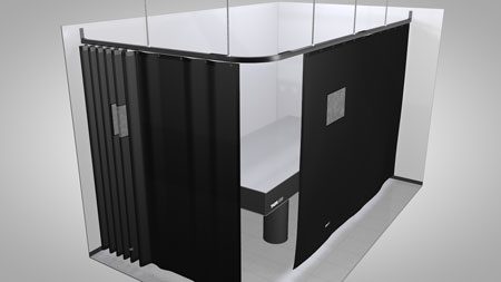 Click to Enlarge The above example configuration is provided to show how our modular laser curtain system can be used in the corner of a lab. This specific example is designed to fit around a 1.2 m x 2.5 m optical table. Click the "View Product List" link above to view all of the items used in this assembly. |
Example 2: Corner of Lab with Stepped Ceiling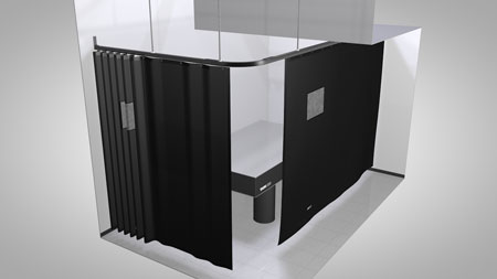 Click to Enlarge The above example configuration is provided to show how our modular laser curtain system can be used in a lab that has a stepped ceiling. This specific example is designed to fit around a 1.2 m x 2.5 m optical table. Click the "View Product List" link above to view all of the items used in this assembly. |
||
Example 3: Covering a Window and Door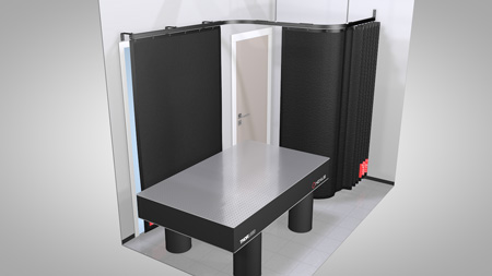 Click to Enlarge The above example configuration is provided to show how our modular laser curtain system can be used in a lab to cover both a window and doorway. The track is laid out such that the door has room to open and close freely behind the curtain. Click the "View Product List" link above to view all of the items used in this assembly. |
Example 4: Central Area in Lab - Ceiling Mounted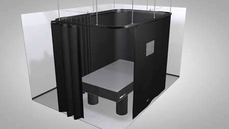 Click to Enlarge The above example configuration is provided to show how our modular laser curtain system can be configured to encompass a central area in the lab. This specific example is designed to fit around a 1.2 m x 2.0 m optical table. Click the "View Product List" link above to view all of the items used in this assembly. A version of this configuration is also available as a kit if you own a Nexus® Optical Table Frame and Overhead Shelving Unit. See our laser safety curtain kit page for complete details. |
||
Example 5: Split Lab Space into Three Sections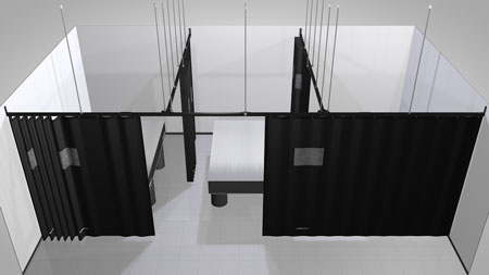 Click to Enlarge The above example configuration is provided to show how our modular laser curtain system can be configured to divide a lab into three sections. Each of the three sections in this example is designed to fit around a 1.2 m x 2.5 m optical table. Click the "View Product List" link above to view all of the items used in this assembly. |
Example 6: Split Lab Space into Four Sections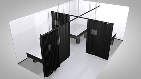 Click to Enlarge The above example configuration is provided to show how our modular laser curtain system can be configured to divide a lab into four sections. Each of the four sections in this example is designed to fit around a 1.2 m x 2.5 m optical table. The complete parts list is provided above. |
||
Example 7: Central Area in Lab - Floor Mounted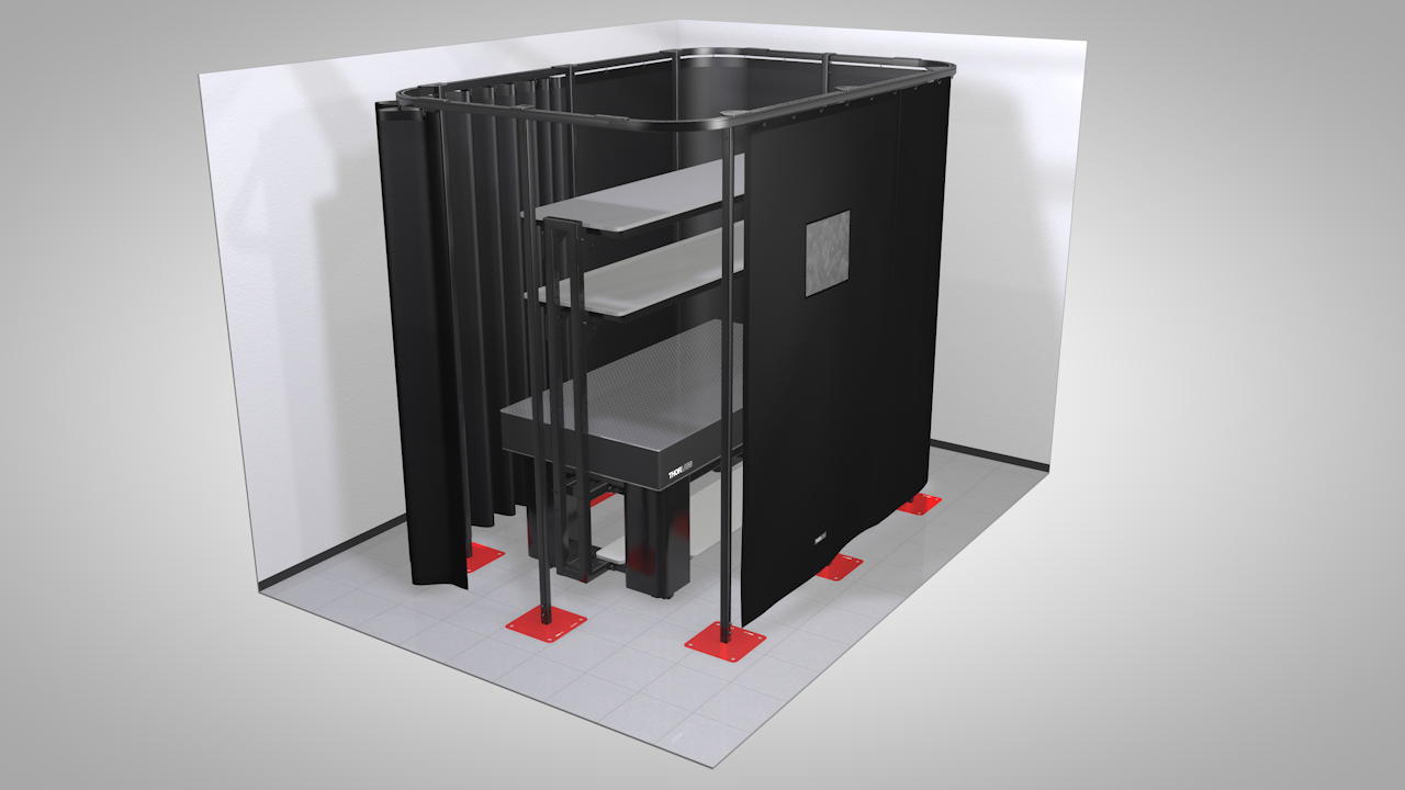 Click to Enlarge The above example configuration is provided to show how our modular laser curtain system can be used to isolate a central area in a lab. This specific example is designed to fit around a 1.2 m x 2.5 m optical table. Click the "View Product List" link above to view all of the items used in this assembly. |
Example 8: Surrounding a ScienceDesk™ Click to Enlarge |
||
Example 9: Dividing a Lab Click to Enlarge The above example configuration is provided to show how our modular laser curtain system can be used to divide sections of a lab. This specific example shields an entryway from a work area. Click the "View Product List" link above to view all of the items used in this assembly. |
Example 10: Corner of Lab - Wall and Floor Mounted Click to Enlarge
|
Laser Safety and Classification
Safe practices and proper usage of safety equipment should be taken into consideration when operating lasers. The eye is susceptible to injury, even from very low levels of laser light. Thorlabs offers a range of laser safety accessories that can be used to reduce the risk of accidents or injuries. Laser emission in the visible and near infrared spectral ranges has the greatest potential for retinal injury, as the cornea and lens are transparent to those wavelengths, and the lens can focus the laser energy onto the retina.
Safe Practices and Light Safety Accessories
- Laser safety eyewear must be worn whenever working with Class 3 or 4 lasers.
- Regardless of laser class, Thorlabs recommends the use of laser safety eyewear whenever working with laser beams with non-negligible powers, since metallic tools such as screwdrivers can accidentally redirect a beam.
- Laser goggles designed for specific wavelengths should be clearly available near laser setups to protect the wearer from unintentional laser reflections.
- Goggles are marked with the wavelength range over which protection is afforded and the minimum optical density within that range.
- Laser Safety Curtains and Laser Safety Fabric shield other parts of the lab from high energy lasers.
- Blackout Materials can prevent direct or reflected light from leaving the experimental setup area.
- Thorlabs' Enclosure Systems can be used to contain optical setups to isolate or minimize laser hazards.
- A fiber-pigtailed laser should always be turned off before connecting it to or disconnecting it from another fiber, especially when the laser is at power levels above 10 mW.
- All beams should be terminated at the edge of the table, and laboratory doors should be closed whenever a laser is in use.
- Do not place laser beams at eye level.
- Carry out experiments on an optical table such that all laser beams travel horizontally.
- Remove unnecessary reflective items such as reflective jewelry (e.g., rings, watches, etc.) while working near the beam path.
- Be aware that lenses and other optical devices may reflect a portion of the incident beam from the front or rear surface.
- Operate a laser at the minimum power necessary for any operation.
- If possible, reduce the output power of a laser during alignment procedures.
- Use beam shutters and filters to reduce the beam power.
- Post appropriate warning signs or labels near laser setups or rooms.
- Use a laser sign with a lightbox if operating Class 3R or 4 lasers (i.e., lasers requiring the use of a safety interlock).
- Do not use Laser Viewing Cards in place of a proper Beam Trap.
Laser Classification
Lasers are categorized into different classes according to their ability to cause eye and other damage. The International Electrotechnical Commission (IEC) is a global organization that prepares and publishes international standards for all electrical, electronic, and related technologies. The IEC document 60825-1 outlines the safety of laser products. A description of each class of laser is given below:
| Class | Description | Warning Label |
|---|---|---|
| 1 | This class of laser is safe under all conditions of normal use, including use with optical instruments for intrabeam viewing. Lasers in this class do not emit radiation at levels that may cause injury during normal operation, and therefore the maximum permissible exposure (MPE) cannot be exceeded. Class 1 lasers can also include enclosed, high-power lasers where exposure to the radiation is not possible without opening or shutting down the laser. |  |
| 1M | Class 1M lasers are safe except when used in conjunction with optical components such as telescopes and microscopes. Lasers belonging to this class emit large-diameter or divergent beams, and the MPE cannot normally be exceeded unless focusing or imaging optics are used to narrow the beam. However, if the beam is refocused, the hazard may be increased and the class may be changed accordingly. |  |
| 2 | Class 2 lasers, which are limited to 1 mW of visible continuous-wave radiation, are safe because the blink reflex will limit the exposure in the eye to 0.25 seconds. This category only applies to visible radiation (400 - 700 nm). |  |
| 2M | Because of the blink reflex, this class of laser is classified as safe as long as the beam is not viewed through optical instruments. This laser class also applies to larger-diameter or diverging laser beams. |  |
| 3R | Class 3R lasers produce visible and invisible light that is hazardous under direct and specular-reflection viewing conditions. Eye injuries may occur if you directly view the beam, especially when using optical instruments. Lasers in this class are considered safe as long as they are handled with restricted beam viewing. The MPE can be exceeded with this class of laser; however, this presents a low risk level to injury. Visible, continuous-wave lasers in this class are limited to 5 mW of output power. |  |
| 3B | Class 3B lasers are hazardous to the eye if exposed directly. Diffuse reflections are usually not harmful, but may be when using higher-power Class 3B lasers. Safe handling of devices in this class includes wearing protective eyewear where direct viewing of the laser beam may occur. Lasers of this class must be equipped with a key switch and a safety interlock; moreover, laser safety signs should be used, such that the laser cannot be used without the safety light turning on. Laser products with power output near the upper range of Class 3B may also cause skin burns. |  |
| 4 | This class of laser may cause damage to the skin, and also to the eye, even from the viewing of diffuse reflections. These hazards may also apply to indirect or non-specular reflections of the beam, even from apparently matte surfaces. Great care must be taken when handling these lasers. They also represent a fire risk, because they may ignite combustible material. Class 4 lasers must be equipped with a key switch and a safety interlock. |  |
| All class 2 lasers (and higher) must display, in addition to the corresponding sign above, this triangular warning sign. |  |
|
| Posted Comments: | |
Sharon McGarvey
(posted 2023-06-29 08:07:36.203) PLease confirm lead time for LPCP78 curtain.
Thanks do'neill
(posted 2023-06-30 09:05:32.0) Response from Daniel at Thorlabs. I will reach out to you directly about this. In general if you click the lead time hyperlink next to the part name this will be the fastest way of requesting the lead time. user
(posted 2019-06-04 07:48:04.817) Hello, I would like to place an optical table with some low-power Vis and IR lasers (5 mW) in the corner of an existing lab. I need laser safety curtains to "isolate" this corner from the rest of the lab, where people are working without laser safety glasses. My question is about the curtain height: should the curtains extend from the floor to the ceiling or is a 2.2/2.4 m height enough? Also, keeping in mind the low power of the lasers in use, is a blackout curtain enoguh protective? Thanks AManickavasagam
(posted 2019-06-05 06:56:44.0) Response from Arunthathi at Thorlabs: Thanks for your query. The blackout curtains are not certified to provide laser protection, so we could guarantee a light tight set up but not to be laser-safe. The height you would require would depend on the direction of your beam path and the reflective surfaces you will have in your setup. user
(posted 2019-04-18 07:13:23.74) Hello, I am Min of ITI.
I am writing to ask something about Laser safety curtain.
We need 2 curtains.
When we checked the details of that, The size of Laser safety curtain is 2.9 x 2.4m. (https://www.thorlabs.com/thorproduct.cfm?partnumber=LPCP108)
But we need 2.9 x 2.7m size.
Please let me know whether you can produce this size of Laser safety curtain or not.
I am waiting for your reply.
Thank you for reading. YLohia
(posted 2019-04-18 10:46:24.0) Hello Min, thank you for contacting Thorlabs. For custom item inquiries, please click on the red "Request Quote" button above. We have reached out to you directly to discuss the possibility of offering this. ivan.skachko
(posted 2019-01-28 12:28:02.07) Can the switches for an interlock system be installed on the curtains somehow?
Thanks
Ivan AManickavasagam
(posted 2019-01-28 10:22:15.0) Response from Arunthathi @ Thorlabs: Thanks for your inquiry. Unfortunately at the moment we are unable to support an interlock laser curtain system but we aim at looking into this for future. I have contacted you directly for further details. |

| Curtain Material Certifications | |
|---|---|
| Wavelength | Certificationa |
| D AB10 I AB5 R AB4 M AB4 |
|
| D AB7 | |
| R AB6 I AB8 M AB8 |
|
| D AB5 | |
| D AB4 I AB5 R AB2 |
|

Click to Enlarge
Wheel runner shown being added to a curtain track. Each curtain includes one wheel runner for each eyelet.
- Certified to EN 12254: 2010(E)*
- Flame Retardant
- Magnetic Strips Connect Curtains for Light-Tight Seal
- Document Pocket and Protection Level Information Provided on Curtain
- Wheel Runners Included (Replacements Available Below)
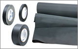
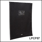
Thorlabs' Laser Safety Curtains are certified to EN 12254: 2010(E); certification levels can be found in the table to the right. Each curtain is made using a rubber compound fabric and includes a 380 mm x 280 mm document pocket on the front of the curtain. The back of the curtain includes the Item # as well as a red label detailing safety compliance information, manufacturing date, and protection level information. The panels can be connected to each other using magnetic strips that are sewn along the vertical edge of each curtain, providing a light-tight seal. Curtains are available from stock in two lengths (2.13 m and 2.44 m) and three widths (1.45 m, 2.14 m, and 2.90 m).
The curtains include one wheel runner for each eyelet. To mount a curtain onto a track, available above, simply insert the wheel runners into the track's bottom channel, as shown in the image to the right. When choosing a laser curtain, we recommend ordering enough so that the combined width is roughly 7% - 10% longer than the overall length of the curtain tracks. This allows the curtains to be draped along the length of the track, ensuring that the lab area will be properly enclosed.
*DISCLAIMER
The curtain materials have been tested by a third party using EN specifications; see the Certifications tab for details. Due to manufacturing variances, mechanical wear, and laser damage, Thorlabs assumes no responsibility for laser curtain failure. Please consult your local laser safety specialist before purchasing to ensure that the curtain is suitable for your application. To minimize risk, inspect the curtain before each use and ensure that it is in excellent condition.

| Valance Material Certifications | |
|---|---|
| Wavelength | Certificationa |
| D AB10 I AB5 R AB4 M AB2 |
|
| D AB7 | |
| R AB7 I AB8 M AB8 |
|
| D AB5 | |
| D AB3 I AB4 R AB2 |
|
- Certified to EN 12254: 2010(E)*
- Flame Retardant
- Product Information Label Provided on Valance
- Track and Rod Mounting Kits Available Separately
Thorlabs' Laser Safety Valance Panel is certified to EN 12254: 2010(E); certification levels can be found in the table to the right. The valance panel is made using a rubber compound and is designed to cover any gaps between laser safety curtains and the curtain tracks or the ceiling. The back of the valance displays the Item # and manufacturing date on a product information label. The valance panel is available from stock in dimensions of 1.2 m wide by 0.4 m high and can be overlapped to cover the required area.
Two separately available kits allow for the valance panels to be mounted on both curtain tracks and mounting rods. It is recommended that at least two mounting clips are used to support each valance panel, with an additional clip used when installing the panels on a curved track. Each kit also comes with a set of 10 connector clips, which can be used to secure overlapping valance panels to each other, preventing gaps in coverage. When ordering valance panels, we recommend allowing for an overlap of at least 10 cm between panels to prevent light leakage; if using the connector clips, an overlap of 15 cm is needed to allow the rigid support bars in each valance panel to overlap. Please see the manual for detailed mounting instructions.
*DISCLAIMER
The valance materials have been tested by a third party using EN specifications; see the Certifications tab for details. Due to manufacturing variances, mechanical wear, and laser damage, Thorlabs assumes no responsibility for laser safety valance failure. Please consult your local laser safety specialist before purchasing to ensure that the valance is suitable for your application. To minimize risk, inspect the valance before each use and ensure that it is in excellent condition.


Click to Enlarge
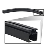
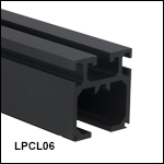
Each track contains a top channel for mounting adapters, two side channels for end stops and T-nuts, and one bottom channel for wheel runners.
Click to Enlarge
LPCC90 Curved Track
- Straight or Curved Tracks to Support Laser Safety Curtains
- Combine Tracks to Create Custom Configurations
- Top Slot Enables Wall, Floor, or Ceiling Mounting Using Accessories Below
These aluminum tracks are designed to support the laser safety curtains sold above. Straight tracks are available in six lengths, while a curved, 90° track allows the system to wrap around corners. Track connectors (sold below) allow sections of track to be combined to create customized curtain systems in a variety of sizes (see the Example Configurations tab above). Dowel pin holes at ends of each track accept dowel pins included our track connectors, ensuring proper alignment.
The bottom of each track provides a path for the curtain wheel runners, while a slot in the top of the track allows the system to be mounted to the wall, floor, or ceiling using the accessories sold below. LPC05 curtain end stops (also sold below) can be added to the system using the side channels in each track.
When mounting a curtain system, we recommend installing track supports for every 1 m of track when using ceiling supports and every 1.2 m of track when using floor supports. Please contact Thorlabs Tech Support with any questions about how to configure a system for your lab.
| Track Options | |||||||
|---|---|---|---|---|---|---|---|
| Type | Straight | Curved, 90° | |||||
| Item # | LPCL06 | LPCL08 | LPCL10 | LPCL12 | LPCL14 | LPCL16 | LPCC90 |
| Track Length | 0.6 m (1.97 ft) |
0.8 m (2.63 ft) |
1.0 m (3.28 ft) |
1.2 m (3.94 ft) |
1.4 m (4.59 ft) |
1.6 m (5.25 ft) |
0.64 ma (2.09 ft)a |

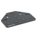
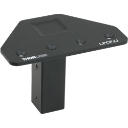
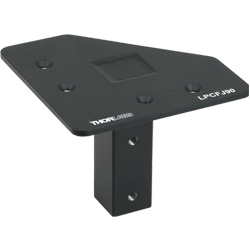
Various track connectors are provided to connect together two, three, or four curtain tracks (sold above) with our various floor, ceiling, and/or wall mounting elements (sold below) for construction of a curtain system. Most track connectors include mounting slots or additional brackets to help attach the curtain system to a wall, ceiling, or floor element. The tables list the track connectors, the type of track connection they provide, the mounting elements with which they are compatible, and additional information needed to decide the appropriate component needed for your setup.
| Track Connectors | |||||
|---|---|---|---|---|---|
| Mounting | Ceiling | ||||
| Product Photoa (Click for Details) |
 |
 |
 |
 |
 |
| Item # | LPC12 | LPC13 | LPC09 | LPC10 | LPC11 |
| Track Connection | Two-Way | 90º (Corner) | Three-Way (T-Joint) | Four-Way | |
| Additional Details | |||||

| Included Hardware | |
|---|---|
| Base | Columns |
| M8 Cap Screw (x2) | N/A |
| M8 Washer (x2) | |
| Specifications | |
|---|---|
| Item # | Height |
| LPCFC7 | 2200.0 mm (86.61") |
| LPCFC8 | 2505.0 mm (98.62") |
- Mounting Base to Affix Curtain System to a Floor
- Painted Red to Increase Visibility When Working
- Mounting Columns for Floor Mounting Curtains
- LPCFC7: Compatible with 2.13 m (83.9") Long Laser Curtains
- LPCFC8: Compatible with 2.44 m (96.1") Long Laser Curtains
- Attach to LPCFB12 Base Using Included M8 Cap Screws
- Mount LPCFJS Track Support and Select Track Connectors
- Hardware Used to Fix Mounting Base to Floor Not Included*
The LPCFB12 Mounting Base is used to mount the modular laser saftey curtain system to the floor. Each base accepts an LPCFC7 or LPCFC8 mounting column, which can be used with a 2.13 m or 2.44 m laser curtain, respectively. They can then accept a track support or track connector to start forming the frame of your laser system. The mounting column attaches to the mounting base using a 6 mm hex key (not included) and included M8 cap screws and washers.
We recommend a support column and base for every 1.2 m of track.
*Due to different building codes, material types, and room designs, hardware to mount this system to floors is not included with any of our curtain system products. Please choose screws and fittings which are suitable for use in your floor and have enough holding power. For reference, chosen hardware should be able to withstand shear forces of approximately 30 N (6.7 lbf) and tensile forces of approximately 440 N (98.9 lbf). If you are uncertain, please contact a local specialized retailer. It is not recommended to use this system before bolting the base plates to the floor.


Click to Enlarge
LPCFJS Support Shown Attached to a Curtain Track
| Included Hardware | |
|---|---|
| M6 Cap Screw (x2) | |
| M8 Cap Screw (x2) | |
| M8 Washer (x2) | |
| Half Joint Plate |
- Supports a Single Curtain Track
- Attaches Directly to a Mounting Column Using Included M8 Cap Screws
- Attaches to Top Channel of Curtain Track for Support Using Included M6 Cap Screws
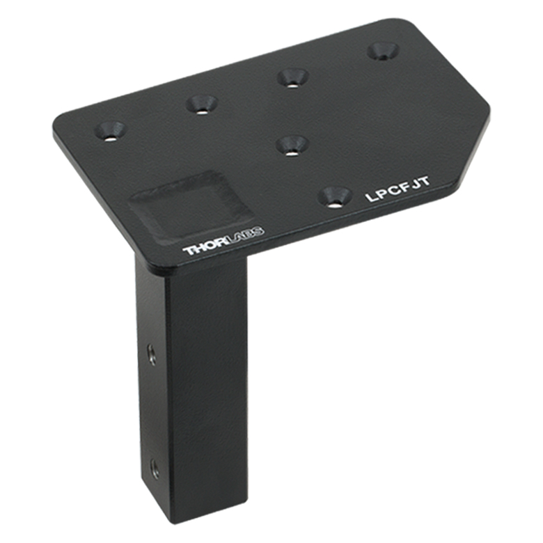
The LPCFJS Rail Support is used to provide additional support for the tracks. The LPCFJS attaches to a
mounting column (sold above) using a 6 mm hex key (not included) and included M8 screws. It then attaches to a curtain track using a 4 mm hex key (not included) and included M6 screws.
When floor mounting a curtain system, we recommend the use of a floor mounted support every 1.2 m.

Click to Enlarge
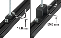
The LPC04 and LPC16 allow vertical adjustment of the track, when using the LPC02 rod, by an amount equal to or less than the track-to-ceiling separation of the bracket.
Click to Enlarge
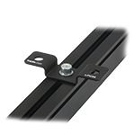
LPC04 Mounted on a Track so that it can be Attached 14.0 mm from a Ceiling
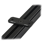
Click to Enlarge
LPC08 Mounted on a Track so that it can be Attached 6.0 mm from a Ceiling
| Included Hardware | ||
|---|---|---|
| LPC08 | LPC04 | LPC16 |
| M8 Countersunk Cap Screw (x1) | M8 Cap Screw (x2) | |
| M8 T-Nut (x1) | M8 T-Nut (x2) | |
| M8 Washer (x2) | ||
- Mounting Brackets for Attaching a Curtain Track to a Ceiling
- LPC08: 6.0 mm Track-to-Ceiling Separation
- LPC04: 14.0 mm Track-to-Ceiling Separation
- LPC16: 55.0 mm Track-to-Ceiling Separation
- Can be Attached to a Ceiling Using the LPC02 Mounting Rod (Available Below)
- Attaches to Curtain Track Using Two Included M8 Cap Screws and T-Nuts
- Hardware Used to Fix Brackets to the Ceiling is Not Included*
These mounting brackets are used to attach a curtain track to a ceiling. Each bracket attaches to the top-located channel of the curtain tracks using a 6 mm hex key (not included) and included M8 cap screws and T-nuts with the center through hole. This allows the track to be positioned before it is secured in place. Three versions are available, each offering a different track-to-ceiling separation: LPC08 (6.0 mm separation), LPC04 (14.0 mm separation), and LPC16 (55.0 mm separation).
The LPC08, LPC04, and LPC16 each have two through holes, offset from center, that are used to attach the brackets directly to the ceiling. These through holes can also be used with the LPC02 Off-Ceiling Mounting Rod, available below, which allows the curtain track to be mounted up to 2 m below the ceiling. Additionally, when the LPC02 is used with the LPC04 and LPC16, the tracks can be vertically adjusted on the rod by an amount equal to or less than the track-to-ceiling separation of the bracket, without interfering with other components mounted on the track. An example can be seen in the photo to the far right. This adjustment range can be used to level the system or change the height at which it is mounted.
Please note that we recommend adding a ceiling support for every 1 m of track to create a more stable system.
*Due to different building codes, material types, and room designs, hardware to mount these brackets to ceilings is not included. Please be aware of the overall weight of the mounted system and choose screws and fittings that are suitable and have enough holding strength for use in your wall or ceiling. If you are uncertain, please contact a specialized retailer.


Click for Details
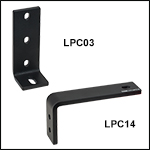
The LPC14 is used to hang a curtain track 138.0 mm from a support wall.
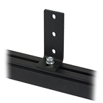
Click for Details
The LPC03 is used to hang a curtain track so that it can be flush with a support wall.
| Included Hardware |
|---|
| M8 Cap Screw (x1) |
| M8 T-Nut (x1) |
| M8 Washer (x1) |
- Mount Curtain Tracks Directly to a Wall for Support
- LPC03: Track Mounted Flush with Wall
- LPC14: Track Mounted 138.0 mm from Wall
- Attaches to Curtain Track Using M8 Cap Screw and T-Nut (Included)
- Hardware Used to Fix Brackets to a Wall is Not Included*
The LPC03 and LPC14 Mounting Brackets are used to attach a curtain track flush with or
138.0 mm from a wall, respectively. Each bracket attaches to the top-located channel of the curtain tracks using a 6 mm hex key (not included) and included M8 cap screw and T-nut, allowing the track to be positioned before it is secured in place. See the images to the right for details.
The LPC03 bracket includes three Ø6.8 mm x 10.0 mm through slots and the LPC14 includes two Ø9.0 mm through holes so that they can be mounted to a wall*.
*Due to different building codes, material types, and room designs, hardware to mount these brackets to a wall is not included. Please be aware of the overall weight of the mounted system and choose screws and fittings that are suitable and have enough holding strength for use in your wall or ceiling. If you are uncertain, please contact a specialized retailer.


Click to Enlarge
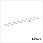
An adapter is included so that the two rods can be attached. This is ideal when the system needs to be attached to higher ceilings.

Click to Enlarge
An M8 threaded T-nut is included so that the rods can be directly attached to a curtain track.
| Included Hardware |
|---|
| M8 Cap Screw (x1) |
| M8 Nut (x5) |
| M8 T-Nut (x2) |
| M8 Adapter Nut (x1) |
| M8 Washer (x4) |
- Ideal for Mounting Curtain Tracks to High Ceilings
- Prevent System Sway when Used with Curtain End Stop Brackets
- Two Externally M8 x 1.25 Threaded, 1.0 m Long Steel Rods Included
- 24.0 mm Long, Internally M8-Threaded Adapter Included to Connect Rods
- Hardware Used to Fix Rods to the Ceiling is Not Included*
The LPC02 Mounting Rod is designed to mount curtain tracks to a high ceiling for support. It can also be attached to a curtain end stop bracket to attach to a far wall to prevent system sway. Please note that the rod is only designed to hold axial loads and should not be used to support loads when mounted horizontally. The LPC02 includes two 1.0 m long steel rods, one 24.0 mm long thread adapter to connect the rods, and mounting hardware, listed in the table to the left, to attach the rod to a curtain accessory.
When mounting to the ceiling, the LPC02 can be attached directly to the top channel of the curtain tracks using the included M8-T-nut or it can be attached to an end stop bracket, available below, using the included M8 lock nuts. When mounting to a wall, the LPC02 will need to be attached to a wall mounting bracket, available above, using the included lock nuts. Please see the manual for detailed wall and ceiling mounting instructions.
Please note we recommend adding a ceiling support for every 1 m of track to guarantee a stable system.
*Due to different building codes, material types, and room designs, hardware to mount these rods to walls or ceilings is not included. Please be aware of the overall weight of the mounted system and choose screws and fittings that are suitable and have enough holding strength for use in your wall or ceiling. If you are uncertain, please contact a specialized retailer.


Click to Enlarge
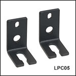
End Stop Shown Attached to the Side of a Curtain Track to Stop the Movement of the Wheel Runners

Click to Enlarge
The LPC05 shown attached to the top of a track with an LPC02 to create a horizontal restraint that prevents swaying of the system.
| Included Hardware |
|---|
| M4 Cap Screw (x2) |
| M4 Drop-In T-Nut (x2) |
| M4 Washer (x2) |
- Provides a Hard Stop for Curtain Panels
- Attaches to the Side Channels of the Curtain Track Using the Provided M4 Cap Screw and T-Nut
- Can be Placed at Any Location Along the Curtain Track
The LPC05 is used to provide a hard stop for a curtain mounted to a track. As shown in the image to the right, it is designed to attach to the side channel of the curtain track using the provided drop-in nut and M4 cap screw. The drop-in nut can be placed into the channel from anywhere on the track; it does not need to be slid in on the end of the track.
When the curtain's wheel runner is in place, the end stop can be positioned with the bottom slot around the hook of the wheel runner. The end stop and held wheel runner can then be adjusted along the length of the curtain track by loosening the M4 cap screw that secures the end stop in place.
The LPC05 can also be attached to the top channel of the curtain track to provide additional wall support for the curtain system. See the image to the right for details and the manual for specific, step-by-step mounting instructions.

| Included Hardware | |
|---|---|
| LPCVH1 | LPCVH2 |
| Mounting Clip (x10) | |
| Connector Clip (x10) | |
| M4 Cap Screw (x20) | M6 Screw (x20) |
| M4 Drop-In T-Nut (x20) | Clamp Body (x10 Pairs) |
| Clamp Base (x10) | |
| 2.5 mm Hex Key (x1) | 4 mm Hex Key (x1) |
- Two Kits for Mounting Valance Panels
- LPCVH1: Compatible with Curtain Tracks
- LPCVH2: Compatible with Mounting Rods
- Each Kit Supports Installation of 10 Mounting Clips for Mounting up to 5 Valance Panels
- Connector Clips allow Panels to Securely Overlap
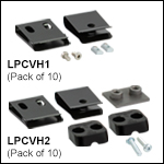
Thorlabs' Valance Mounting Hardware Kits allow our valance panels to be installed in curtain systems that use our curtain tracks or curtain mounting rods. Each kit comes with 10 mounting clips to support the valance panels, as well as 10 connector clips which allow valance panels to be securely overlapped to prevent gaps in coverage. It is recommeded that two clips are used to support each panel, with an additional clip needed when installing on a curved track. An appropriate hex key is also included.
The LPCVH1 Track Mounting Kit is designed for use with our curtain tracks. This kit comes with 20 M4 drop-in T-nuts, which can be inserted into the side channel of the curtain tracks to accept the included M4 cap screws. Two screws can then be used to secure a mounting clip, which will help support the valance panels. The kit allows for a total of 10 mounting clips to be installed for mounting of up to five valance panels.
The LPCVH2 Rod Mounting Kit is designed for installation on our LPC02 mounting rods. This kit comes with 10 pairs of clamp bodies, which are each secured around a mounting rod by actuating two M6 screws throught the clamp body pair and into a clamp base. These screws can then be used to secure a mounting clip to support the valance panel. Each kit allows for 10 mounting clips to be installed to support mounting up to five valance panels. If the addition of valance panels necessitates additional support in a rod-mounted system, more LPC02 mounting rods are available separately on this page.
Please see the manual for detailed mounting instructions.


Click to Enlarge
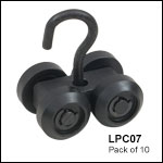
Wheel runners shown being added to a curtain track. Each laser curtain includes one wheel runner for each eyelet.
The LPC07 contains a pack of 10 replacement wheel runners that are used to attach the laser safety curtains to a curtain track. First, insert the wheels of the LPC07 into the bottom channel of the curtain track. Then slide the hook of the wheel runner into the eyelet of the laser curtain.
Please note that Thorlabs' laser safety curtains come with one wheel runner for each eyelet in the panel.


Click to Enlarge
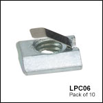
M8-Threaded T-Nuts are Used in the top Channel of the Curtain Tracks to Attach Mounting Adapters and Track Connectors
The LPC06 contains a pack of 10 T-Nuts that can be used in the top channel of the laser curtain tracks. These T-Nuts effectively add M8 tapped holes to the laser curtain track, which allows the track connectors, mounting rods, and wall/ceiling mounting brackets in our modular curtain system to be mounted. They can also be used to replace the T-Nuts included in our Laser Curtain Kits to connect the tracks to the main support frame.
Please note that T-Nuts are provided with each laser curtain accessory.
 Products Home


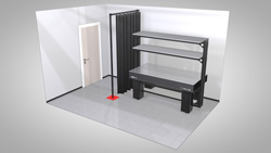
 Click to Enlarge

 Zoom
Zoom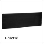


 Laser Safety Curtains