 Products Home
Fiber-to-Fiber Couplers with Adjustable Path Length

- Reflective, Achromatic Design for 450 nm - 20 µm
- Ideal for Ø200 to Ø1000 µm Core MM Fibers with ≤0.50 NA
- Free-Space Beam Path Up to 500 mm
- Available with FC/PC or SMA Connectors
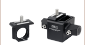
RLAFC1S
Fiber-to-Fiber Coupler with Adjustable Path Length, Ø1" Max Beam Diameter, FC/PC Connectors
Application Idea
Additional components can be added into the free-space region of the adjustable path length fiber-to-fiber coupler for applications that require light filtering or sample interaction.


Please Wait

Click to Enlarge
The RLAFC1F Fiber-to-Fiber Coupler is used with a CFW6(/M) filter wheel and GCA50 Acetylene Glass Reference Cell to measure the Acetylene spectral response.
Features
- Adjustable Path Length Fiber-to-Fiber Coupling Rail System Utilizing Ø1" Off-Axis Parabolic (OAP) Mirrors
- Protected Silver Coating (450 nm - 20 µm) for Broadband Sources
- Typical Insertion Loss ≤2.1 dB for Collimator Spacing ≤500 mm (See Specs Tab for Compatible Fiber Details)
- Available with Either 2.2 mm Wide Key FC/PC or SMA905 Ports
- Compatible with 30 mm Cage Systems and SM1-Threaded Components
- 1/4" (M6) Counterbored Holes and Slots for Rail Mounting Flexibility
- Laser-Engraved Scale for Precise Construction
- Dovetail RLA Rail Design Accommodates Our Cage-Compatible Dovetail Mounts, Snap-on Carriers, and Mounting Accessories
Thorlabs' Adjustable Path Length Fiber-to-Fiber Couplers are ideal for fiber-based spectroscopic applications. As shown in the diagram to the right, this adjustable coupling system is composed of two mounted collimators and an RLA series dovetail rail. Two off-axis parabolic (OAP) mirrors are used to collimate the light out of the input fiber and couple it into the output fiber. The separation between the two collimators is adjustable up to 500 mm, which allows additional components to be inserted into the free-space beam path for applications that require sample interaction, spectral filtering, or light manipulation.
The use of OAP mirrors provides high reflectance, high NA, and achromatic performance over the reflection band. For more information about the OAP mirrors, please see the Specs tab. The all-reflective design eliminates phase delays and absorption losses introduced by transmissive optics. The mirrors and fiber bulkheads are pre-aligned in RLA rail carriers to produce a collimated multimode beam along the rail axis and couple it back into fiber. Please note that the collimator mounts are sold together as a serialized pair; specifications are not guaranteed for mixed pairs. See the Insertion Loss tab for more details on how the insertion loss is impacted by wavelength, fiber type, and collimator spacing.
These collimators feature a dovetail adapter for mounting onto the dovetail of the included RLA series rail (Item # RLA1200), allowing for precise alignment and positioning of optical elements in the beam path. The beam height is aligned 50.0 mm above the top surface of the rail. The collimator mounts are each equipped with four through holes for ER Series Cage Construction Rods that are compatible with our 30 mm Cage Sytems, adding further options for straightforward optic alignment. Cage rods (not included) can be secured in these holes by four M4 x 0.7 locking setscrews, which can be tightened with a 5/64" (2.0 mm) hex key. The collimators each also feature SM1 (Ø1.035"-40) internal threading for straightforward mounting of SM1-threaded components.
For custom fiber bulkheads, mirror coatings, or filter holders, please contact Tech Support.
Fiber Compatibility
Thorlabs' Adjustable Path Length Fiber Couplers are designed to work with multimode patch cables with core diameters from 200 - 1000 µm and NA ≤0.5. In general, the mounts are not intended for use with single-mode to single-mode fibers due to the sub-micron precision necessary for SM fiber-to-fiber coupling. However, a single mode fiber can be used as the input of the mount provided that the output is connected to a multimode fiber.
Mounting Options
The rail contains several 1/4" (M6) counterbored holes for mounting to a breadboard. The mirrors are very sensitive to angular misalignment, so the rail should be mounted on a very flat surface and care should be taken not to twist or otherwise deflect the rail when mounting to a breadboard. We recommend tightening screws gently, one at a time while pushing the rail against the screws. These rails can also be clamped to an optical table or breadboard using our CL6 table clamps. The collimators can be locked in place on the rail via a side-located clamping screw that can be secured using a 5/64" (2.0 mm) hex key.
| Item # | RLAFC1F | RLAFC1S |
|---|---|---|
| Compatible Fiber Connector | 2.2 mm Wide Key FC/PC | SMA905 |
| Input Fiber NA | ≤0.5 NA | |
| Typical Insertion Lossa (No Additional Filters) |
≤2.1 dB @ 450 nm - 20 µm | |
| Beam Height | 50.0 mm (1.97") |
|
| Dimensions (Collimator) | 2.08" x 1.50" x 2.94" (52.7 mm x 38.1 mm x 74.7 mm) |
2.18" x 1.50" x 2.94" (55.4 mm x 38.1 mm x 74.7 mm) |
| Dimensions (Including Rail) | 2.08" x 12.00" x 3.14" (52.7 mm x 304.8 mm x 79.8 mm) |
2.18" x 12.00" x 3.14" (55.4 mm x 304.8 mm x 79.8 mm) |
| Included Rail | RLA1200 | |
| Off-Axis Parabolic Mirror Specificationsb | ||
| Coating | Protected Silver | |
| Reflectance (Average) Click for Plot |
>97%, 450 nm - 2 µm >95%, 2 - 20 µm |
|
| Off-Axis Angle | 90° | |
| Clear Aperture | Ø0.90" (22.8 mm) | |
| Reflected Focal Length | 1.0" (25.4 mm) | |
Beam Diameter After Collimation

Click to Enlarge
Diagram of the Beam Path Through Through the Adjustable Path Length Fiber Coupler
Beam diameter can be calculated very easily using the numerical aperture of the fiber (NA) and the reflected focal length of the OAP. To calculate the beam diameter in the small angle approximation, use the following equation:
Beam Diameter = 2 x NA (Fiber) x Reflected Focal Length
The table below lists the output beam diameter as a function of the reflected focal length of the mirror and the numerical aperture of the fiber. The clear aperture of the OAP should be larger than the desired beam output diameter.
| Fiber NA | Beam Diameter | OAP Clear Aperture | |
|---|---|---|---|
| 0.10 | 0.20" | Ø0.90" (22.8 mm) | |
| 0.20 | 0.40" | ||
| 0.39 | 0.78" | ||
| 0.50 | 1.00"a | ||
Adjustable Fiber-to-Fiber Collimator Insertion Loss
Various tests were performed to demonstrate the specified insertion loss of the RLAFC1F and RLAFC1S Fiber-to-Fiber Couplers and how it is affected by a number of variables. Click the links below for more information about a specific test.
- Insertion Loss vs. Wavelength
- Determine the effect of wavelength on insertion loss.
- Insertion Loss at Mode-Stripped and Overfilled Launch Conditions
- Determine how insertion loss is affected by fiber core diameter for different fiber launch conditions.
- Inserton Loss vs. Collimator Spacing
- Determine how the insertion loss changes as a function of the spacing between the two collimators in each fiber-to-fiber coupler.
Insertion Loss vs. Wavelength
The graphs below compare the insertion loss vs. wavelength for different fiber types. The shaded region denotes the lower end of the specified wavelength range and the specified insertion loss of the adjustable fiber-to-fiber couplers. Insertion loss at any given wavelength is also dependent upon the properties of the fiber used and is measured without any additional optics in the beam path. Generally, issues with insertion loss are most severe at short wavelengths and are stable at higher wavelengths.

Click to Enlarge
Click for Raw Data
The above plot shows the typical insertion loss versus wavelength for the adjustable path length fiber couplers set with a 38 mm path length when MIR multimode fiber patch cables are used with a mode-stripped fiber launch. This can then be compared to the performance of a low-OH silica fiber patch cable and a theoretical lossless fiber. This data was taken using Thorlabs' SLS202L Broadband Light Sourcea with OSA201C and OSA207C Optical Spectrum Analyzers.

Click to Enlarge
Click for Raw Data
The above plot shows the typical insertion loss versus wavelength for the adjustable path length fiber couplers set with a 38 mm path length when used with various 0.22 NA silica fiber patch cables. Note that even for the Ø50 µm core fiber and fiber bundle, the insertion loss is still around 3 dB. This data was taken using Thorlabs' SLS201L Broadband Light Source and CCS200 Spectrometer. Because the data is measured using a spectrometer, the measured insertion loss is similar to that for a mode-stripped fiber launch (see below for details of the mode-stripped fiber launch condition).
Insertion Loss at Mode-Stripped and Overfilled Launch Conditions
The graphs below compare the performance of fibers used with the adjustable path length fiber couplers under different launch conditions. A mode-stripped (70/70) fiber launch condition removes cladding modes that are lost in the coupler while an overfilled (>100%) fiber launch condition contains all propagating modes. For the mode-stripped fiber launch, a pinhole is placed in front of the LED source at a position where the beam spot at the fiber face is 70% of the core diameter and is diverging at an angle which is 70% of the fiber NA. Because measuring the input and output power using a power meter does not allow for discrimination of these mode types, a mode-stripped launch condition is a better measurement of the actual insertion loss of the fiber couplers.

Click to Enlarge
Click for Raw Data
The above data was taken to show the negative effects of overfilling the input fiber (defined above). In this plot, the pinhole used in the mode-stripped example to the left was removed and the LED output was sent directly into the silica fiber. The output from the fiber coupler (with 38 mm collimator spacing) was then coupled into an S120C Power Meter.

Click to Enlarge
Click for Raw Data
The above data was taken using a mode-stripped fiber launch (defined above) with silica fiber. To achieve these conditions a pinhole with a diameter 70% of the fiber core was placed after the output of a previous-generation M470F3 Fiber-Coupled LED. The output from the fiber coupler (with 38 mm collimator spacing) was then coupled into an S120C Power Meter. This plot shows similar results compared to using a single mode laser source or mandrel wrapping method.
Insertion Loss vs. Collimator Spacing
The graphs below compare the insertion loss vs. separation distance between the two collimators for different fiber types. The specified insertion loss, indicated by a horizontal dotted black line, is valid for mount spacing below 500 mm. Data is not shown for separations smaller than 85 mm since the curves remain relatively flat and variation at this level is dominated by rail alignment. Insertion loss at any given wavelength is also dependent upon the properties of the fiber used and is measured without any additional optics in the beam path.

Click to Enlarge
Click for Raw Data
The above data was taken using an M470F4 Fiber-Coupled LED with the output coupled into an S120C Power Meter. These couplers perform well for a wide range of fiber core sizes with 0.39 NA; even for fiber cores greater than Ø1000 µm, the insertion loss at shorter distances stays under 2 dB.

Click to Enlarge
Click for Raw Data
The above data was taken using an M470F4 Fiber-Coupled LED with the output coupled into an S120C Power Meter. These couplers perform well for a wide range of fiber core sizes with 0.22 NA, but greater losses are intoduced with fibers cores smaller than Ø200 µm.
Click to Enlarge
Click for Raw Data
The above data was taken using an M470F4 Fiber-Coupled LED with the output coupled into an S120C Power Meter. These couplers perform well for a wide range of fiber core sizes with 0.50 NA.
| Posted Comments: | |
| No Comments Posted |