 Products Home
Fiber Optic Power Meters with Internal Sensor
- Wavelength Ranges: 400 nm to 1700 nm
- Power Ranges: -70 dBm to 23 dBm
- Interchangeable Fiber Connector
- Options Available for Integrated Visual Fault Locator
PM60A
Fiber Optic Power Meter
400 - 1100 nm
Easy-to-Read Large
Digital Touchscreen Display
PM61 Series Power Meter with Included Fiber Adapter Removed
Additional SM05-Threaded Fiber Adapters Available Separately
PM20-SMA
PM20-ST


Please Wait
| PM60 and PM61 Series Features | ||
|---|---|---|
| Item # | PM60 Series | PM61 Series |
| Rechargeable Battery |  |
|
| Fast Charging vis USB-C Connector | |
|
| Embedded Wireless Charging Coil | - | |
| Data Storage to Internal Flash Memory | |
|
| Internal Flash Memory Access via USB | |
|
| Pass / Fail Analysis | - | |
| Admin / User Levels | - | |
| Physical Menu Button Configuration | - | |
| Visual Fault Locator (VFL) | - | |
| USB 2.0 Full Speed Interface | |
|
| Bluetooth Low Energy Connectivity | - | |
| OPM Software Compatible | |
|
Click to Enlarge
A PM61CH power meter with a fiber-optic patch cable (sold separately) attached to the detector port is shown above.
| Power Meter Selection Guide |
|---|
| Sensors |
| Photodiode Power Sensors |
| Thermal Power Sensors |
| Thermal Position & Power Sensors |
| Pyroelectric Energy Sensors |
| Power Meter Consoles and Interfaces |
| Digital Handheld Console |
| Analog Handheld Console |
| Touchscreen Handheld Console |
| Dual-Channel Benchtop Console |
| USB Interfaces with External Readout |
| Complete Power Meters |
| Power Meter Bundles |
| Wireless Power Meters with Sensors |
| Compact USB Power Meters |
| Field Power Meters for Terminated Fibers |
Fiber Optic Power Meter Features
- Si (PM6xA) or InGaAs (PM6xC or PM6xCH) Sensors
- Wavelength Range:
- 400 nm - 1100 nm (Si)
- 800 nm - 1700 nm (InGaAs)
- Power Ranges:
- -65 dBm to 16 dBm (300 pW - 40 mW) for PM6xA
- -70 dBm to 13 dBm (100 pW - 20 mW) for PM6xC
- -55 dBm to 23 dBm (3 nW - 200 mW) for PM6xCH
- Interchangeable Fiber Connectors:
- PM20-25 2.5 mm Ferrule Adapter Included
- FC/PC, FC/APC, SC, ST®, LC, or SMA Adapters Sold Separately Below
- Absolute and Relative Measurements Displayed in dBm, dB, pW, nW, µW, mW, and W
- NIST- and PTB-Traceable Wavelength Calibration
- Digital Menu Navigation via Physical Buttons and Capacitive Touchscreen
- Optical Power Meter PC Software Available (See Software Tab for Details)
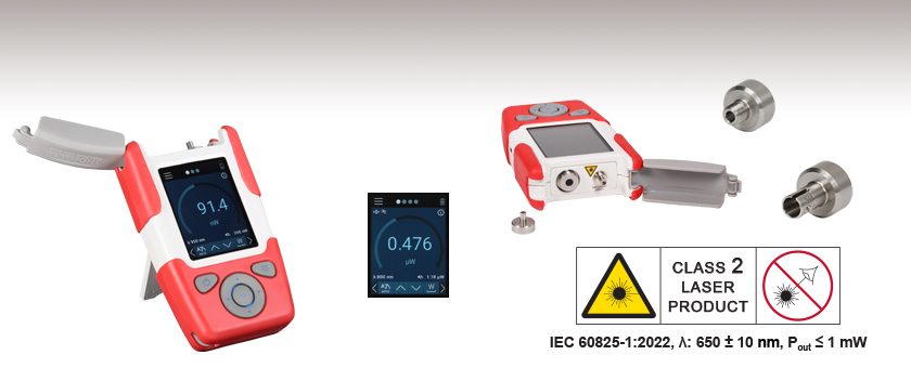
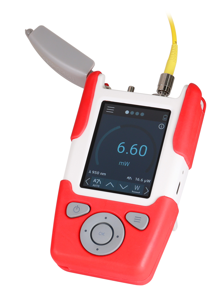
The PM60 and PM61 Series of Fiber Optic Power Meters are robust, full-featured, handheld instruments, which together cover the full range of optical fiber applications within the 400 - 1700 nm range with optical powers ranging from -70 dBm to +23 dBm (100 pW - 200 mW). A rugged enclosure, internal sensors, kickstand, and hand strap eyelet (hand strap not included) make these models ideal for field or lab applications. The PM60A and PM61A power meters use a Si sensor for detection between 400 nm and 1100 nm, while the PM60C, PM60CH, PM61C, and PM61CH use an InGaAs sensor for detection between 800 nm to 1700 nm.
Each unit is shipped with a PM60 or PM61 series power meter with an attached PM20-25 fiber adapter, USB cable (Type A to Type C), Certificate of Calibration, and Quick Reference.
Device Design
The PM60 and PM61 series power meters can be operated using both a 2.8" capacitive touchscreen and the physical keys shown in the image above. An interactive GUI is available for download to demo all the features (see the Interactive Demo tab). Each power meter comes with a USB C rechargeable, lithium polymer (LiPo) battery with a 2300 mAh capacity. The PM61 series power meters feature an additional wireless charging capability via an inductive charging coil. Each power meter is shipped with an SM05 (0.535"-40) internally threaded PM20-25 adapter for fiber patch cables with 2.5 mm ferrules. The PM20-25 adapter is designed without a locking mechanism to allow for fast and efficient power measurements using patch cables with a variety of terminations.
The PM61 series power meters are equipped with a Visual Fault Locator (VFL) consisting of a 650 nm class 2 guide laser and 2.5 mm ferrule receptacle which can be used to find fibers in a bundle, breaks in a fiber, or alignment into an optical fiber. The VFL can be used in a continuous wave (CW), 1 Hz flashing, or 3 Hz flashing setting.
Remote Operation
The PM60 and PM61 series power meters can be controlled remotely using Thorlabs' Optical Power Monitor (OPM) software. Both series feature a USB 2.0 interface to connect to a PC. Additionally, the PM61 series has a built in Bluetooth module that allows the user to establish a wireless connection to a PC. Remote connectivity allows the user to access the power meter settings, visualize power measurements, and record data directly through the OPM software. Please see the Software tab for details.
Analysis Tools
The Fiber Power Meter Series offer Data Logging and Statistics analysis tools which allow for power levels over a specified time period to be recorded and saved on the internal memory to be accessed at a later time using the USB connection and an external PC. The Data Logging tool shows a time trace of the power levels over the given interval while the Statistics tool shows the number of samples, elapsed time and mean, maximum, and minimum power levels. The PM61 series also features the Pass / Fail Analysis tool which gives a visual indication to whether a given measurement is within a predefined power range.
*ST® is a registered trademark of Lucent Technologies, Inc.
| Item #a | PM60A, PM61A | PM60C, PM61C | PM60CH, PM61CH |
|---|---|---|---|
| Sensor Specifications | |||
| Optical Power Range | -65 dBm to 16 dBm (300 pW - 40 mW) |
-70 dBm to 13 dBm (100 pW - 20 mW) |
-55 dBm to 23 dBm (3 nW - 200 mW) |
| Spectral Range | 400 - 1100 nm | 800 - 1700 nm | |
| Detector Type | Silicon | InGaAs | |
| Sensor Size | 3.6 x 3.6 mm | Ø3 mm | |
| Aperture Thread | SM05 Thread (0.535"-40) for Fiber Adapters 2.5 mm Ferrule Adapter Included (Item # PM20-25) |
||
| Measurement Uncertainty | ±0.25 dB | ||
| Measurement Standard | NIST / PTB Traceable | ||
| General Device Specifications | |||
| Display Type | 2.8" IPS with Capacitive Touchscreen | ||
| Power Ranges | 21 Current Ranges from 2 nA to 10 mA, Represented in Watts | ||
| Power Units | dBm, dB, pW nW, µW, mW, W | ||
| Resolution | 16 bits | ||
| Sample Rate | Up to 100 kS/s via USB | ||
| Dimensions (H x W x D) w/ Holster | 136.0 mm x 79.0 mm x 34.4 mm (5.35" x 3.11" x 1.32") |
||
| Weight | 0.25 kg (0.55 lbs) | ||
| Operating Temperature | 5 °C to 40 °C | ||
| Storage Temperature | -20 °C to 70 °C | ||
| Power Management | |||
| Battery Operation | Internal LiPo Battery Pack, 2300 mAh, 3.7 W | ||
| Charger | USB C, Inductive Charging Coil (PM61 Series Only), 5 W | ||
| Remote Operation | |||
| Interface | USB 2.0 with USB Type C Connector Bluetooth Low Energy (PM61 Series Only) |
||
| Data Storage | |||
| Internal Memory | eMMC (≥4 GB), Accessible via USB C | ||
| Visual Fault Locator (PM61 Series Only) | |||
| Wavelength | 650 nm | ||
| Output Power | ≤1 mW (Class 2 Laser) | ||
| Operation | CW, Flashing: 1 Hz, 3 Hz | ||
| Connector | 2.5 mm Ferrule | ||
Interactive Downloadable Demo

Click to Enlarge
Screenshot of the Downloadable Interactive GUI
An interactive GUI is available for download to demo all the features of the PM60 and PM61 Series Power Meters. For computers with a touchscreen, the demo supports all swipe gestures to switch screens. Otherwise, a mouse or dirctional keyboard and enter keys can be used to interact with these functions. The GUI provides the opportunity to browse all submenus and change settings. For information on navigating the measurement and menu screens, please see the PM60 and PM61 Series Power Meter manual.
The demo offers access to all the features of the PM60 or PM61 series power meters that are selectable while using either the touchscreen or the physical keypad with limited configurability. The simulated measured power level can be set over several decades and simulated measurements can be performed displaying as it would on the physical device.
Download Information
Click the button below to download the PM60_Demo.exe file required to run the interactive GUI. This GUI requires a computer running Windows 7 or later.
File Size: 2.6 MB
Compatible Power Meters
- Consoles:
- PM100A Analog Power and Energy Meter Console
- PM100D Digital Power and Energy Meter Console
- PM400 Capacitive Touchscreen Power and Energy Meter Console
- PM5020 Dual-Channel Benchtop Optical Power and Energy Meter Console (Version 4.0 or Later)
- Complete Power Meters:
- PM160, PM160T, and PM160T-HP Wireless Handheld Power Meters with Bluetooth® Technology
- PM16 Series Compact USB Power Meters
- PM60 and PM61 Fiber Optic Power Meter Series (Version 6.0 or Later)
- Interfaces:
- PM101 Series Power Meter Interfaces with External Readout (Version 2.0 or Later)
- PM102 Series Power Meter Interfaces with External Readout (Version 2.1 or Later)
- PM103 Series Power Meter Interfaces with External Readout (Version 3.0 or Later)
- PM100USB USB Interface Digital Power and Energy Meter
Optical Power Monitor
The Optical Power Monitor GUI software features power measurement, readout from up to eight power meters, and remote wireless operation.
For details on specific software features, please see the user manual.
Users interested in the legacy Power Meter Software can find it by visiting the software page.
The PM101 Series Power Meters are only compatible with version 2.0 or later. The PM102 Series Power Meters are only compatible with version 2.1 or later. The PM103 Series Power and Energy Meters are only compatible with version 3.0 or later. The PM5020 Console is only compatible with version 4.0 or later. The PM60 and PM61 Power Meter Series are only compatible with version 6.0 or later.
Optical Power Monitor GUI Software for Touchscreen, Handheld, and USB-Interface Power Meters
Features
- Operate up to Eight Power Meters Simultaneously
- Record and Analyze Measurements in Real Time
- Intuitive Analog Display and Graphing Modes
- Configurable Long-Term Data Logging
- Also Supports Position Measurements with Thermal Position & Power Sensors
- Compatible with USB and Bluetooth® Connections
The Optical Power Monitor software GUI enables seamless control of up to eight power meters that are connected via USB, RS232, or Bluetooth® wireless technologya. The latest software, firmware, drivers, and utilities for these power meters can be downloaded here.
Multiple data measurement and analysis functions are integrated into the GUI package. The interface offers a user-friendly design with minimal use of color and low brightness that is ideal use in dark lab environments while wearing laser safety glasses. Measured data can be displayed in real time as a simulated analog needle, digital values, line graph, or bar graph. Continuously logged and short-term measurements can be recorded for data viewing and analysis at a later point. A built-in statistics mode analyzes measured data and continuously updates to reflect new measurements within the pre-determined measurement period. Beam position measurements are also supported when used with our thermal position & power sensors.
The Optical Power Monitor software package installs the GUI, which then can be used to control the touchscreen, handheld, or USB-interface power meters. Firmware updates for supported power meters are also available. Programming examples and drivers for interfacing with our power and energy meter consoles using LabVIEW, C/C++, Visual C#, and Python are installed with the software; refer to the manual for details.
Please note that the Optical Power Monitor Software uses different drivers than the Power Meter Utilities Software and Thorlabs recommends using the new driver TLPM.dll. For users who wish to use the legacy Power Meter Software or use custom software designed using the older PM100D.dll driver, a Power Meter Driver Switcher program is included for easy swapping of the installed driver between the two versions.
a. The PM61 Series, PM160, PM160T, and PM160T-HP power meters are equipped with Bluetooth® connections.

Click to Enlarge
Power Measurement Mode: Set up and configure up to eight power meters.

Click to Enlarge
Power Tuning Mode: Simulated analog needle and digital measurement value provided. Delta Mode, enabled above, shows the fluctuation range during the measurement period.

Click to Enlarge
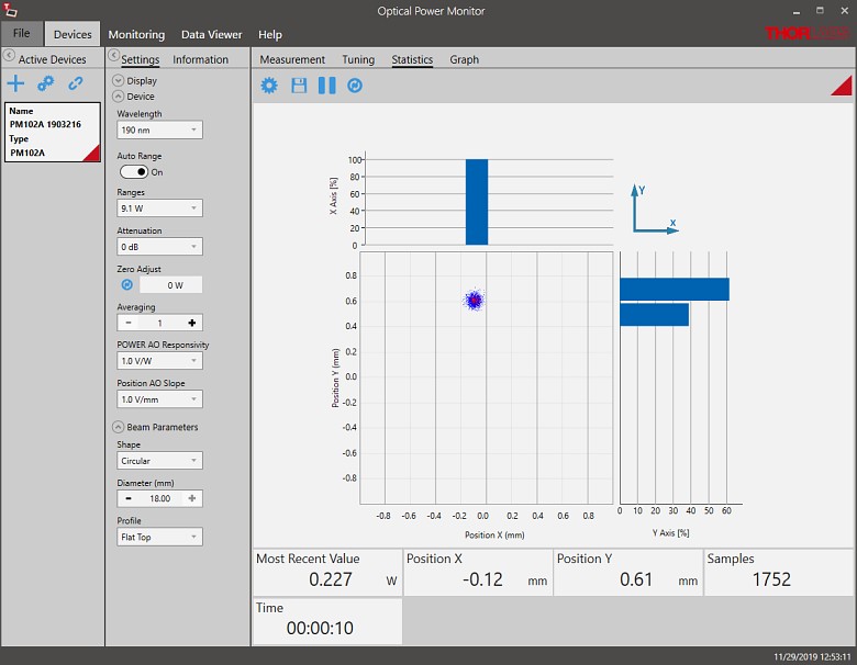
Power Statistics Mode: Calculate numerical statistics for a pre-determined measurement period. The panel displays the analyzed values in a bar graph and the results as numerical values.

Click to Enlarge
Position Tuning Mode: Tuning mode can be used with a thermal position & power sensor to aid in beam alignment.
Click to Enlarge
Position Statistics Mode: Statistics mode also provides aggregate information for thermal position & power sensors.

Click to Enlarge
Data Logging: Enable long-term measurement and simultaneous recording from up to eight power meters. Save data as .csv files for later processing while measurement results are displayed in a graph in real time.
Pulsed Laser Emission: Power and Energy Calculations

Determining whether emission from a pulsed laser is compatible with a device or application can require referencing parameters that are not supplied by the laser's manufacturer. When this is the case, the necessary parameters can typically be calculated from the available information. Calculating peak pulse power, average power, pulse energy, and related parameters can be necessary to achieve desired outcomes including:
- Protecting biological samples from harm.
- Measuring the pulsed laser emission without damaging photodetectors and other sensors.
- Exciting fluorescence and non-linear effects in materials.
Pulsed laser radiation parameters are illustrated in Figure 1 and described in the table. For quick reference, a list of equations are provided below. The document available for download provides this information, as well as an introduction to pulsed laser emission, an overview of relationships among the different parameters, and guidance for applying the calculations.
|
Equations: |
||||
 |
and |  |
||
 |
||||
 |
||||
 |
||||
Peak power and average power calculated from each other: |
||||
 |
and |  |
||
| Peak power calculated from average power and duty cycle*: | ||||
 |
*Duty cycle ( ) is the fraction of time during which there is laser pulse emission. ) is the fraction of time during which there is laser pulse emission. |
|||

Click to Enlarge
Figure 1: Parameters used to describe pulsed laser emission are indicated in the plot (above) and described in the table (below). Pulse energy (E) is the shaded area under the pulse curve. Pulse energy is, equivalently, the area of the diagonally hashed region.
| Parameter | Symbol | Units | Description | ||
|---|---|---|---|---|---|
| Pulse Energy | E | Joules [J] | A measure of one pulse's total emission, which is the only light emitted by the laser over the entire period. The pulse energy equals the shaded area, which is equivalent to the area covered by diagonal hash marks. | ||
| Period | Δt | Seconds [s] | The amount of time between the start of one pulse and the start of the next. | ||
| Average Power | Pavg | Watts [W] | The height on the optical power axis, if the energy emitted by the pulse were uniformly spread over the entire period. | ||
| Instantaneous Power | P | Watts [W] | The optical power at a single, specific point in time. | ||
| Peak Power | Ppeak | Watts [W] | The maximum instantaneous optical power output by the laser. | ||
| Pulse Width |  |
Seconds [s] | A measure of the time between the beginning and end of the pulse, typically based on the full width half maximum (FWHM) of the pulse shape. Also called pulse duration. | ||
| Repetition Rate | frep | Hertz [Hz] | The frequency with which pulses are emitted. Equal to the reciprocal of the period. | ||
Example Calculation:
Is it safe to use a detector with a specified maximum peak optical input power of 75 mW to measure the following pulsed laser emission?
- Average Power: 1 mW
- Repetition Rate: 85 MHz
- Pulse Width: 10 fs
The energy per pulse:

seems low, but the peak pulse power is:

It is not safe to use the detector to measure this pulsed laser emission, since the peak power of the pulses is >5 orders of magnitude higher than the detector's maximum peak optical input power.
| Posted Comments: | |
user
(posted 2024-03-29 16:32:54.717) I have a PM20C instrument, and I found that when using the instrument without the adapter, a certain value is measured. However, when the adapter is connected, the value decreases. What causes this? dpossin
(posted 2024-04-02 06:42:00.0) Dear customer,
Thank you for your feedback. I will reach out to you directly to discuss this with you. Jose Manuel Suarez
(posted 2023-10-04 10:49:25.067) Hi! I work in the optical lab at Royal Observatory of the Navy in San Fernando (Spain) and had an issue using this power meter. I had an OVERFLOW reading when measuring 515nm green light of around 20mW (measured also with PM100D power meter without problem). It is supposed that measuring range is up to 40mW, so it was strange.
Thanks in advance, regards. hkarpenko
(posted 2023-10-10 10:37:32.0) Dear Jose,
thank you for your feedback. I will contact you directly to discuss this issue with you. qiaozhanduo qiao
(posted 2023-02-15 00:15:13.913) 还有个问题需要咨询,脉冲激光器的平均功率在量程范围内时,脉冲峰值功率小于五倍的最大平均功率,探测器就是安全的吗? hkarpenko
(posted 2023-02-16 07:48:56.0) Dear customer,
thank you for your feedback. In general you are right, the peak power and average power should be well under the power range of the sensor. Measuring pulsed laser sources with a photodiode can be challenging, since you would need a higher repetetion rate to measure the correct power. I will contact you directly to discuss this further with you. user
(posted 2022-12-01 13:14:02.81) We have a PM20A powermeter and want to use it to measure the light intensity (400-800 nm) coming out of a ferrule (the fiber has a 0.2 NA). What distance do you recommend between the ferrule and the sensor? And what is the optimal diameter the light beam must have on the sensor? hchow
(posted 2022-12-01 10:32:43.0) Dear Customer, thank you for your feedback. The distance between the ferrule while encapsulated in a FC/PC fiber adapter to the sensor's plane is 3.7 +/- 0.3 mm. If you remove the fiber adapter, then from the surface of the diode connector's surface to the sensor is 3.2 mm. While the beam diameter on the surface of the sensor is given by this equation: expanded beam at PD surface = 2*( 3.7*Tan(NA))+core size. Thank you. Francis Guay
(posted 2021-07-13 02:49:14.527) Does Thorlabs provide a calibration Service for this device? MKiess
(posted 2021-07-15 06:08:10.0) Dear Francis, thank you for your inquiry. Yes we offer calibration service for this fiber optic power meter. If you wish to do so, please send an e-mail with the article number and the serial number of the desired power meter to rma.de@thorlabs.com. Afterwards we will send you all further information for sending in the meter for calibration. If you have any further technical questions regarding calibration, please feel free to contact our Tech Support. dayana A
(posted 2019-10-22 14:37:04.1) Does Fiber Optic Power Meters have Built in Backlight feature ? dpossin
(posted 2019-10-24 08:47:59.0) Hello Dayana,
Thank you for your feedback! In case you mean a backlight for the display, unfortunately we currently do not offer this feature. Priya R
(posted 2019-10-21 22:45:44.04) Hi,
Is PM20CH integrated into a single unit for display and Keypad? MKiess
(posted 2019-10-25 09:31:06.0) This is a response from Michael at Thorlabs. The Thorlabs PM20CH is a complete, easy to use fiber-optic power measurement system with built-in optical sensor.
It has five operating keys and a display with which you can make all possible settings on the device itself. user
(posted 2019-04-15 10:14:54.383) Hi! We have recently bought a PM20CH power meter almost a month ago. Initially just to check the device it was working properly. But while doing the experiments and with its constant use it is found that if the battery is full it works fine when no charger is attached to it but the moment you plug the charger it shows a constant smudged display which seems to be CHARGING and the screen is fixed with it and one can't do any measurements.
What might be the reason for it?
The device is certainly under warranty period. swick
(posted 2019-05-15 03:32:15.0) This is a response from Sebastian at Thorlabs. The "charging" should disappear on the display after few seconds.
As you did not left contact details on this feedback, please contact your local Thorlabs Office for immediate help. user
(posted 2018-11-20 01:52:38.42) Hi!
Actually I have been trying to measure and verify the power of a fiber laser which has a power stability of 0.1 % with PM20 CH fiber optic power meter but the reading of the power meter fluctuates and is not providing a stable output power reading.
Can you please specify the stability of the power measured by this PM20CH power meter? nreusch
(posted 2018-11-28 05:51:35.0) This is a response from Nicola at Thorlabs. Thank you for your inquiry! I am sorry to hear that you are not able to get a stable output reading. Unfortunately, we only specify an absolute uncertainty of +/-0.25 dB. The stability and repeatability of the PM20CH are definitely lower than this value. As you did not leave any contact information, please contact your local Tech Support team to discuss wavelength, absolute power and extent of fluctuations you are observing to check whether your PM20CH shows a normal behavior. jan0dirk.lueuer
(posted 2018-08-26 13:17:06.387) Can this powermeter be used to measure short pulses (around 200 ns)?
We tried measuring powers (approx. 150 mW) and see a lot less power than we get using power heads. nreusch
(posted 2018-08-29 06:59:26.0) This is a response from Nicola at Thorlabs. Thank you very much for your inquiry. The PM20A contains a Silicon photodiode sensor. We do not recommend measuring nanosecond sources with this type of sensor. I will contact you directly to discuss alternative options. srikanth
(posted 2018-07-11 04:04:48.793) What are implications for power measurements FC/APC connected pigtails?
What are resolution (optical power) and linearity of the power meter?
Is the power meter calibrated over entire wavelength range in steps of 5nm?
LDT of 50W/cm^2 for (PM20CH) turns out to be ~32dBm; please confirm. swick
(posted 2018-07-13 05:26:30.0) This is a response from Sebastian at Thorlabs. Thank you for the feedback.
The linearity is +/- 0.5 % and the resolution depends on the power range but is basically 14 bit.
For using FC/APC connectors we recommend to use PM20-FC as fiber adapter.
The calibration step size is 5 nm over entire wavelength range.
The damage threshold is specified to be 50 W/cm² which is not necessarily equal to +32dBm because not the complete sensor size gets illuminated in most cases. This finally depends on the fiber type used. ana.cardenas
(posted 2018-06-19 13:50:16.06) We aquired a PM20CH and we would like to know if it is possible to get an adapter for free space measurements. mvonsivers
(posted 2018-06-21 08:05:20.0) This is a response from Moritz at Thorlabs. Thank you for your inquiry. The PM20 series is only designed for fiber coupled measurements, however, for free space beams the fiber adapter could just be removed. Dee1g12
(posted 2017-11-22 18:06:31.78) Can the charger be bought separately?
If so, how much do they cost?
Thanks,
Sincerely,
-David- mvonsivers
(posted 2017-11-27 08:42:52.0) This is a response from Moritz at Thorlabs. Thank you for your inquiry. Currently we do not offer a replacement power supply as standard product. However, any power supply with the following specifications can be used: 12V, 850mA, 2.1mm/5.5mm plug. I will contact you directly for further information. schaefer
(posted 2017-02-15 14:08:06.713) Hi! We have used a P20A unit for a long time and it seems like the battery has suffered quite a bit - after recharging it until 'battery is full' it takes only a couple of minutes until it says 'battery low' and with the AC plugged in there is a constant 'charging' text getting in the way of the actual measurement. Is there any way to replyce the battery or at least turn of the recharging message blinking? wskopalik
(posted 2017-02-21 03:16:46.0) This is a response from Wolfgang at Thorlabs. Thank you very much for your inquiry.
Yes, we can exchange the battery in these powermeters. I have contacted you directly to arrange the exchange. nicholas.sinclair
(posted 2014-08-21 08:36:54.13) Just a follow-up to the previous response about the active area of the PM20A. The specs on the webpage say 3.6 mm^2, but the manual says (3.6 mm x 3.6 mm), which is correct?
Since you mentioned the possibility of the beam being too large at the sensor, I'm curious what is the max acceptable NA for a single-mode fiber to avoid this issue (or if you could just tell me the approximate distance from the fiber tip to the sensor).
Thanks! shallwig
(posted 2014-08-22 10:04:06.0) This is a response from Stefan at Thorlabs. Thank you very much for your inquiry.The sensor size is like stated in the manual on page 10 3.6mm x 3.6mm http://www.thorlabs.com/thorcat/14100/PM20A-Manual.pdf I am sorry if the information on the website were confusing here. The distance between ferule and detector plane is 3,7 +/- 0,3mm.
I will contact you directly to discuss you application in detail. user
(posted 2014-04-17 17:17:37.477) Dear Tech-support,
could you please confirm if PM20A is compatible with standard 1mm POF (@650nm and 850nm)?
best regards
Michal shallwig
(posted 2014-04-25 04:12:55.0) This is a response from Stefan at Thorlabs. Thank you very much for your inquiry. To decide if a fiber is suitable we would need to know the NA and diameter, since it is possible to over illuminate the sensor. We specify the sensor size with 3.6 mm^2 active area. If the beam is larger, in the plane of the sensor, you will loose light and measure accuracy will be effected. Also, the damage threshold of the sensor may be an issue. We specify a damage threshold of 50 W/cm2.
If your fiber has one of the standard connectors, you can exchange the FC/PC adapter for one of the adapters we provide as accessories on our website: http://www.thorlabs.de/newgrouppage9.cfm?objectgroup_id=906.
Regarding the wavelength range, both 650nm and 850nm lie within the specified wavelength range of the built-in Si detector. To discuss in more detail the compatibility of your specific light source + fiber unit with our PM20A I will like to contact your directly. bdada
(posted 2011-12-13 11:59:00.0) Response from Buki at Thorlabs:
We have contacted you to get more information about your request. p_a_t_g
(posted 2011-12-13 09:32:37.0) Gentlemen
The power to put has function of guarded information jjurado
(posted 2011-03-22 10:43:00.0) Response from Javier at Thorlabs to anjonslay: Thank you very much for your interest in our products. A representative from our China sales office will contact you directly with pricing and availability information for our PM20C power meter. You can also reach this office via phone or e-mail:
Phone: +86 (0)21-32513486 or +86 (0)21-32513482
Email: chinasales@thorlabs.com anjonslay
(posted 2011-03-22 17:24:06.0) ??!
?????????????????????????:PM20C - Fiber Power Meter,?????:PM20-FC - FC Fiber Adapter Cap with internal SM05 Thread?????,????????????,???????????????!?????????????????????????????????????????!?????!??!
??????!
??/????/?????? deriksson
(posted 2009-12-28 09:27:01.0) PM20A passar utmärkt för att mäta effekten ur en laser diod med den effekt och vågläng som du vill mäta.
PM20A är lättanvänd och effekten läses ut direkt på displayen
Till PM20A finns dessutom olika fiber adaptrar under sectionen Accessories.
The PM20A will work perfect for measuring the power of the laser diode you want to measure.
The PM20A is easy to use and the power can be read directly on the display.
Different fiber connectors are available under the section Accessories mats
(posted 2009-12-27 13:19:08.0) Hej - jag jobbar med laserbehandlingar mot tunnhårighet. Vi vill nu jämföra lasrar på marknaden. Alla lasrar på denna marknad säger sig ge 5mW av 650nm våglängd. Dioderna är fastsatta på plattor så jag måste ha en bärbar enhet för att komma åt att mäta eller om det finns någon fiberadapter att sätta mot dioden och att mätinstrumentet står på ett bord bredvid.
Tror ni att ni har någon sådan produkt för oss? Det är inte superprecision jag är ute efter men absolut ingen leksak heller.
Mats Stolt 0701 910 110 - 08 20 00 18 technicalmarketing
(posted 2008-01-04 11:56:03.0) The PM20C does indeed come with a FC-adaptor. That item is available under the "accessories" section in case you need to purchase another one. The ST adaptor is avilable using the orer code (PM20-ST). Shortly, you will also see an LC adapter featured on this page (PM20-LC). We hope this information is helpful and apologize for the confusion. ruudg
(posted 2008-01-04 05:52:49.0) dear madam/sir
recently I have ordered a PM20C from you, plus some extra adaptors.
there is some small discrepancy here:
in the specs from the PM20C it says that it comes with an FC adaptor included, and that SC, ST and SMA can be ordered as extras. however in the list of extras you can only choose FC (again?) SC and SMA. can you please check with what standard adaptor the PM20C really comes and/or provide me with an ordering code for the ST-adaptor?
By the way, when will you be delivering the ordred PM20C?
regards,
ruud groenewegen.
royal nioz, netherlands. technicalmarketing
(posted 2007-10-08 10:39:42.0) Thank you for suggestion for this page. We now list power ranges in decibels as well as milliwatts. We hope this added information is helpful. acable
(posted 2007-10-05 20:30:24.0) Since we don't all think in dB can you also provide power range in units of mW. |

 Zoom
Zoom- Handheld Fiber Optic Power Meter for Wavelength Ranges Between 400 - 1700 nm
- 2300 mAh Battery with USB C Charging Cable Included
- Remote Operation Using USB 2.0 Interface
- Internal Data Storage and Access via USB
The PM60 Series Fiber Optic Power Meters are robust, handheld instruments that are ideal for both lab and field applications. Each unit includes a rechargeable 2300 mAh LiPo battery that has the capacity for continuous operation throughout a workday.
The PM60A power meter features an internal Si sensor for measuring wavelengths from 400 nm to 1100 nm at optical powers from -65 dBm to +16 dBm (300 pW - 40 mW). The PM60C and PM60CH power meters both feature an InGaAs sensor for measuring wavelengths from 800 - 1700 nm and are sensitive to optical powers from -70 dBm to +13 dBm (100 pW - 20 mW) and -55 dBm to +23 dBm (3 nW - 200 mW), respectively.

 Zoom
Zoom- Handheld Fiber Optic Power Meter for Wavelength Ranges Between 400 - 1700 nm
- Built-In 650 nm Visual Fault Locator (VFL) Included
- 2300 mAh Battery with USB C Cable and Wireless Charging Included
- Remote Operation Using USB 2.0 or Bluetooth Interface
- Internal Data Storage and Access via USB
The PM61 Series Fiber Optic Power Meters are robust, handheld instruments that are ideal for both lab and field applications. Each unit includes a rechargeable 2300 mAh LiPo battery that has the capacity for continuous operation throughout a workday.
The PM61A power meter features an internal Si sensor for measuring wavelengths from 400 nm to 1100 nm at optical powers from -65 dBm to +16 dBm (300 pW - 40 mW). The PM61C and PM61CH power meters both feature an InGaAs sensor for measuring wavelengths from 800 - 1700 nm and are sensitive to optical powers from -70 dBm to +13 dBm (100 pW - 20 mW) and -55 dBm to +23 dBm (3 nW - 200 mW), respectively.
Each PM61 series fiber optic power meter contains an integrated VFL that emits ≤1 mW at 650 nm and can be used for detecting fibers in a bundle, breaks in an optical fiber, or aid in free-space to fiber alignment. The VFL can be operated in CW, Flashing: 1 Hz, or 3 Hz modes via the touchscreen or physical buttons on the device, or using the OPM software GUI.
Additionally, the PM61 series features user configurable menus along with Admin / User levels to ensure operation is customizable and secure for all users.
These adapters are compatible with devices that feature external SM05 threading such as our S15xC Series Fiber Power Meter Sensors, PM160 wireless power meter, and the Fiber Optic Power Meters above. One PM20-FC wide-key FC/PC fiber adapter is included with each of the power meters sold above. For details on narrow versus wide key connectors, please see our Intro to Fiber tutorial.
The PM20-25 ferrule adapter is designed without a locking connector mechanism and accepts fiber patch cables with Ø2.5 mm ferrules for quick power meter measurements.
| Item # | PM20-FC2 | PM20-FC | PM20-APC2a | PM20-APCa | PM20-SMA | PM20-ST | PM20-SC | PM20-LC | PM20-25 |
|---|---|---|---|---|---|---|---|---|---|
| Adapter Image (Click the Image to Enlarge) |
 |
 |
 |
 |
 |
 |
 |
 |
 |
| Connector Type | FC/PC, 2.0 mm Narrow Key |
FC/PC, 2.2 mm Wide Key |
FC/APC, 2.0 mm Narrow Key |
FC/APC, 2.2 mm Wide Key |
SMA | ST®b/PC | SC/PCc | LC/PC | Ø2.5 mm Ferrule |
| Threading | Internal SM05 (0.535"-40) | ||||||||