K-Cube™ Liquid Crystal Controller
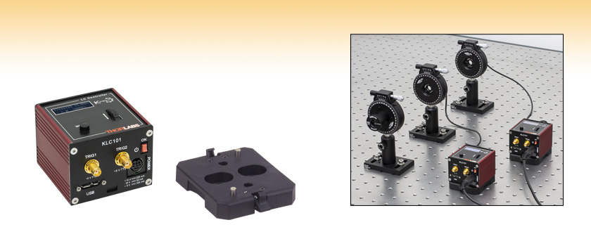
- For Control of LC Polarization Rotators, Cells, and Variable Retarders
- 0 to ±25 VAC, Adjustable Frequency Square Wave Output
- BNC Output Connector
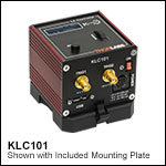
KLC101
Liquid Crystal Controller
(Power Supply Sold Separately)
Table Mounting Plate (Included with KLC101)
Application Idea
Two KLC101 controllers can be used to operate variable retarders so that any polarization state can be achieved

Please Wait

Click to Enlarge
Back and Top Views of the KLC101 K-Cube
(See the Pin Diagrams Tab for More Information)
Features
- Square-Wave Output Voltage with Adjustable Amplitude and Frequency
- 0 to ±25 VAC
- 500 Hz to 10 kHz (50% Duty Cycle)
- Maximum Output Current: 50 mA
- Operating Modes Include:
- Switching Between Two Voltage and Frequency Set Points
at Frequencies of 0.1 to 150 Hz (50% Duty Cycle) - User-Programmable Voltage Sequences
- Trigger Input and Output
- Switching Between Two Voltage and Frequency Set Points
- Edit Settings Using Device Top Panel or Control via USB Input from a PC
- Settings can be Saved to Allow Stand-Alone Operation via Top Panel Controls
- Multi-Unit Operation Using Trigger Ports or USB Controller Hubs (Sold Separately)
- Magnetic, Clip-On Optical Table Mounting Adapter Included
- Compact Footprint: 60.0 mm x 60.0 mm x 46.7 mm
The KLC101 K-Cube Liquid Crystal Controller is a part of Thorlabs' growing line of high-end, compact controllers and is designed to drive many of Thorlabs' liquid crystal variable retarders, polarization rotators, and cells (see the table to the upper right for compatible devices). It supplies a square-wave AC output voltage with user-set frequency and amplitude that can be varied from 500 Hz to 10 kHz and 0 Vrms to ±25 Vrms, respectively. Any DC offset will automatically be detected and corrected to within ±10 mV in real time, helpful for increasing the life of the liquid crystal device. Settings can be input using either the scroll wheel and button on the top panel or a PC connected via the USB port. Alternatively, an input voltage applied to the MOD IN port can be used to control the output voltage (see below for details). Two SMA ports are provided for use with 5 V logic external trigger input and output signals, allowing the voltage output to be synchronized with external equipment. For example, multiple K-cube controllers can be connected together using the trigger inputs and outputs for synchronized, multi-channel system operation.
The unit has a highly compact 60.0 mm x 60.0 mm x 46.7 mm footprint, allowing it to be positioned close to the optical system for added convenience when manually adjusting settings using the top panel controls. Tabletop operation also allows minimal drive cable lengths for easier cable management. Each unit also contains a front-located power switch that, when turned off, saves all user-adjustable settings. Please note that this switch should always be used to power down the unit. For convenience, a 1.5 m long Type A to Type Micro B USB 3.0 cable is included with the KLC101 K-cube.

Click to Enlarge
KCH601 USB Controller Hub with Installed K-Cube Modules
Operating Modes
A variety of operating modes allow the user to set the controller output to a single voltage and frequency, have the device run through a pre-programmed sequence of voltages and frequencies, or synchronize changes in output voltage with other devices.
- Voltage and Frequency Set Points: The controller accepts two user-set voltage and frequency combinations, PresetV1 and Preset V2. Either can be selected as the output, and the user can manually switch between PresetV1 and PresetV2.
- Switching Mode: The user can set the controller to switch between PresetV1 and PresetV2 at rates between 0.1 and 150 Hz using the control panel or software. When in this mode, one of the trigger ports will output a 5 V logic signal, with the high level indicating that the output is PresetV2 and a the low level indicating the output is PresetV1.
- MOD IN Mode: The output voltage of the controller is set by a 0 to 5 V signal applied to the MOD IN port, with 0 to 5 V DC input corresponding to 0 to ±25 Vrms AC output signal.
- Trigger Modes: Either both trigger ports can be configured to provide an output 5 V logic signal output, or one of the trigger ports can be used to read an external 5 V logic signal while the other will output a 5 V logic signal. The high level corresponds to PresetV2, and the low level corresponds to PresetV1.
- Sequence Mode (Software Only): The user can set a sequence of output voltages and frequency. For each step in the sequence, the output voltage amplitude, output frequency, and step duration are editable. The number of times the sequence repeats can also be set by the user.
- Sweeping Mode (Software Only): The user can set a start voltage, end voltage, step size, and step duration, and the KLC101 controller will scan from the start to end point once the user hits "Start" in the GUI. All voltage steps wil have the same output frequency.
Optical Table Mounting Plate
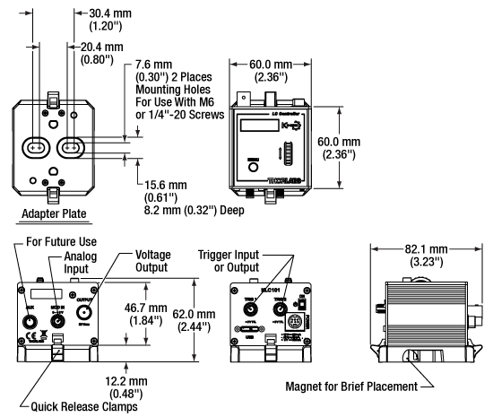
Each unit comes with a plastic mounting plate that clips onto the base of the controller. The plate contains two magnets for temporary placement on an optical table and two counterbores for 1/4"-20 (M6) cap screws for a more permanent placement on the tabletop. Please see the Specs tab for a mechanical drawing of the table mounting plate and the Mounting Options tab for more information about the mounting plate.
Power Supply Options
The preferred power supply (single channel or hub-based) depends on the end user's application and whether you already own compatible power supplies. To that end and in keeping with Thorlabs' green initiative, we do not ship these units bundled with a power supply.
Multiple units can be connected to a single PC by using the KCH301 or KCH601 USB Controller Hubs, available below, for multi-axis motion control applications. The KCH601, shown below and to the right, allows up to six T- or K-Cube controllers to be used while the KCH301 allows up to three controllers to be used.
All power supply options compatible with the KLC101 Liquid Crystal Controller can be found below.
An alternative to the KLC101 K-cube is the LCC25 Benchtop Liquid Crystal Controller.
Click to Enlarge
Mechanical Drawing of the KLC101 and Included Optical Table Adapter
| KLC101 Specifications | ||
|---|---|---|
| Electrical Characteristics | ||
| Adjustable Output Voltage | 0 to ±25 V RMS | |
| Voltage Resolution | 1.0 mV | |
| Adjustable Output Frequency | 500 Hz to 10 kHz, 50% Duty Square Wave |
|
| Adjustable Internal Switching Frequency | 0.1 Hz to 150 Hz at 50% Duty Cycle |
|
| Slew Rate | 10 V/µs | |
| DC Offset | ±10 mV | |
| Warm Up Time | 30 Minutes | |
| USB Port | USB 3.0 Micro B | |
| K-Cube Controller Hub Connector | 26-Way ERNI | |
| Maximum Ratings | ||
| Maximum External Input Voltage | 5 VDC | |
| Maximum External Modulation | 150 Hz | |
| Maximum Output Current | 50 mA | |
| Operating Temperature Range | 10 to 40 °C | |
| Maximum Relative Humidity | 85% | |
| Input Power Requirements | ||
| Voltage (Current) | +15 V (220 mA), -15 V (50 mA), +5 V (350 mA) |
|
| General | ||
| Weight | 140 g (5.0 oz) | |
| Housing Dimensions (W x D x H)a | 60.0 mm x 60.0 mm x 46.7 mm (2.36" x 2.36" x 1.84") |
|
Power Connection:
8-Pin Mini-DIN
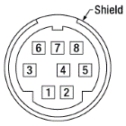
| Pin | Description |
|---|---|
| 1 | +5 V |
| 2 | +5 V |
| 3 | -15 V |
| 4 | +15 V |
| 5 | +5 V |
| 6 | Common Ground |
| 7 | Common Ground |
| 8 | Common Ground |
| Shield | Common Ground |
Computer Connection*

*The USB 3.0 port is compatible with a USB 2.0 Micro B connector if the Micro B connector is plugged into the shaded region in the photo above. A USB 3.0 type A to type Micro B cable is included with the KLC101 controller.
TRIG 1
|
TRIG 2
|
 |
 |
| +5 V TTL | +5 V TTL |
| These connectors provide 5 V logic level input or output to support triggering into and out of external devices. Each port can be configured using the Settings menu on the K-cube's top panel. Both are defaulted to output. When a port is configured to be input, the other will automatically be set to output. | |
MOD IN
|
|
 |
|
| Accepts 0 to +5 V DC External Analog Input | |
K-Cube™ Mounting Options
Two options are available to securely mount our K-Cube™ controllers onto an optical table. An optical table mounting plate, provided with every K-Cube, allows for a single controller to be attached to an optical table. Alternatively, three- and six-port USB controller hubs are offered (sold separately) that can mount and power our K-Cube controllers. These options are described in further detail below.
Optical Table Mounting Plate
Each K-Cube unit comes with a mounting plate that clips onto the base of the controller, as shown in the animation to the right. The plate contains two magnets for temporary placement on an optical table and two counterbores for 1/4"-20 (M6) cap screws for a more permanent placement on the tabletop. Please see the Specs tab for a mechanical drawing of the table mounting plate.
Kinesis USB Controller Hubs
Multiple units can be mounted and connected to a single PC by using the KCH301 or KCH601 USB Controller Hubs. They each consist of two parts: the hub, which can support up to three (KCH301) or six (KCH601) K-Cubes or T-Cubes™, and a power supply that plugs into a standard wall outlet. K-Cubes simply clip into place using the provided on-unit clips, while current- and previous-generation T-Cubes require the KAP101 Adapter Plate, shown in the animation below. The hub vastly reduces the number of USB and power cables required when operating multiple controllers.
K-Cube Table Mounting Plate
Unlike T-Cubes, every K-Cube includes a mounting plate that clips onto the base of the controller. The plate contains two magnets for temporary placement on an optical table and two counterbores for 1/4"-20 (M6) cap screws for more permanent placement on the tabletop.
Kinesis USB Controller Hubs
3- and 6-Port USB Controller Hubs allow multiple controllers to be connected to one PC for multi-axis applications. K-Cubes can be directly attached to the hubs while T-Cubes require a KAP101 Adapter Plate.
Click to Enlarge
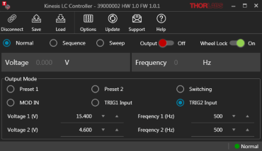
Screenshot of the GUI interface
Software for the KLC101 Controller
The stand-alone software user interface, which is distinct from Thorlabs' Kinesis® software, allows full control of all KLC101 settings and operating modes, enabling complete ‘out-of-box’ operation of a single KLC101 controller. In addition to remotely controlling the settings that can be accessed from the KLC101 top panel, the software also includes Sequence and Sweep modes. The Sequence tool can be used to set a sequence of different output voltage amplitudes, frequencies, and step durations. In Sweep mode, the KLC101 will scan between user-set start and end voltages with a user-specified step size and step duration. The software also comes with a SDK that supports C++, LabVIEW™, and Python.
To control multiple KLC101 units simultaneously requires opening multiple instances of the software. Each instance will ask the user to select the particular K-cube that it will connect to upon opening. Each instance of the software will work independently from the others with no communication between them.
| Posted Comments: | |
user
(posted 2023-05-22 09:21:50.483) Hi,
Is there documentation available regarding the APT Protocol? I know you offer a SDK with a DLL but in your APT_Communications_Protocol documentation there is no reference to the KLC101. Would be nice if you could add it there.
Thank you. cdolbashian
(posted 2023-05-26 12:22:46.0) Thank you for contacting Thorlabs. We will reach out to you directly with our communications protocol document. PAWAN KUMAR
(posted 2022-09-14 19:49:17.08) Hi, Is it possible to configure one of the trigger ports (TRIG1 or TRIG2) to get a trigger pulse out at every step when operating in sequence or sweeping mode? jgreschler
(posted 2022-10-14 01:39:53.0) Thank you for contacting Thorlabs. When TRIG is set to output, it can only provide Hi-Lo voltage that represent the switching between V1 and V2 in switching mode. Where a high level indicates output V2 and a low level indicates output V1. Yujie Zhang
(posted 2022-07-05 23:40:36.003) How to open and use two K-cubes at the same time (KLC 101 with open.vi)?, it seems that it always only open one of them. cdolbashian
(posted 2022-07-19 02:46:23.0) Thank you for contacting Thorlabs, In case of running two devices in parallel, you will need to create two control objects (open.vi), and run both objects in LabVIEW. One open.vi can only open one KLC101. I have posted your feedback to our software team for further consideration to add an example of multi-device operation to the SDK. Mike Lee
(posted 2021-06-15 17:08:08.763) 1. any fan or air blow inside? because I don't want vibration
2. how to cool it?
3. can I write my own C software to control this device?
4. quotations for 1 piece and 12 pieces cwright
(posted 2021-06-15 06:51:25.0) Response from Charles at Thorlabs: Hello and thank you for your query. There is not a fan inside this controller and it is not necessary to provide a source of cooling. The body of the controller acts as a heatsink. It is possible to write your own software using C++. There is an example and a software development kit (SDK) manual in the installation directory. By default it would be found here: C:\Program Files (x86)\Thorlabs\KLC\Sample\Thorlabs_KLC_C++SDK
A quotation can be requested through our website or by contacting your local sales team using the details on the Thorlabs Worldwide Sales and Technical Support Contact Information page: https://www.thorlabs.com/supportcontact.cfm |

- Front Panel Controls and Digital Display
- Software and USB Port for External Control via PC (USB Cable Included)
- Two Bidirectional Trigger Ports for Synchronization with External Equipment
- Compact Footprint: 60.0 mm x 60.0 mm x 46.7 mm (2.36" x 2.36" x 1.84")
- Power Supply Not Included (See Below)
Thorlabs' KLC101 K-Cube Liquid Crystal Controller provides control of the liquid crystal polarization rotators, cells, and variable retarders listed in the Compatible LC Devices table above. The digital display and controls on the top panel can be used to locally set the output voltage amplitude and frequency. The digital display includes a backlight that can be dimmed or turned off using the top panel menu options. Alternatively, a USB port allows the unit to be connected to a computer and controlled using the KLC101 software (available on the Software tab above).
A MOD IN port on the back panel also allows the output to voltage to be controlled using a 0 to 5 V input, with a 5 V input corresponding to a ±25 VAC output. The front of the unit contains two bidirectional trigger ports that can be used to read a 5 V external logic signal or output a 5 V logic signal to control external equipment.
Please note that this controller does not ship with a power supply. Compatible power supplies are listed below.

- Individual ±15 V/5 V Power Supply
- TPS002: For up to Two K-Cubes™ or T-Cubes™ with Mini-DIN Input*
- USB Controller Hubs Provide Power and Communications
- KCH301: For up to Three K-Cubes or T-Cubes
- KCH601: For up to Six K-Cubes or T-Cubes
The TPS002 supplies power for up to two K-Cubes* or T-Cubes. The cubes still require individual computer connection via USB cable.
The KCH301 and KCH601 USB Controller Hubs each consist of two parts: the hub, which can support up to three (KCH301) or six (KCH601) K-Cubes or T-Cubes, and a power supply that plugs into a standard wall outlet. The hub draws a maximum current of 10 A; please verify that the cubes being used do not require a total current of more than 10 A. In addition, the hub provides USB connectivity to any docked K-Cube or T-Cube through a single USB connection.
For more information on the USB Controller Hubs, see the full web presentation.
*The TPS002 can only support one KNA-VIS or KNA-IR controller or one KLD101 driver and should not be used to power any additional units as that may exceed current limitations.
 Products Home


 Zoom
Zoom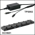
 K-Cube LC Voltage Controller