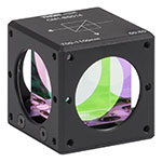
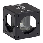
30 mm Cage Cube-Mounted Turning Prism Mirrors

- Metallic- or Dielectric-Coated Turning Prism Mirrors
- Premounted in 30 mm Cage Cubes
- Compatible with SM1 Lens Tubes and 30 mm Cage System
CCM1-G01
4-40 Tapped Holes Provide
Compatibility with Thorlabs’
30 mm Cage System, Rods Sold Seperately

Please Wait
Features
- Choose from Seven Coating Options
- Metallic: UV-Enhanced Aluminum, Protected Aluminum, Protected Silver, Protected Gold
- Dielectric: E02 (450 - 750 nm), E03 (750 - 1100 nm), or K13 Nd:YAG (532 nm and 1064 nm)
- Compatible with Our SM1 Lens Tubes and 30 mm Cage System
- Part Number and Coating are Engraved on the Housing for Easy Identification
- Post Mountable
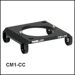
- Connect One Cage Cube-Mounted Turning Prism Mirror to a Different Cage Cube with the CM1-CC Cage Cube Connector
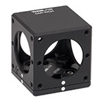
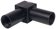
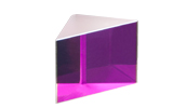
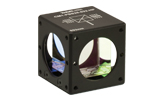
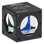
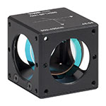
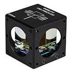
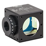
These Cage Cube-Mounted Turning Mirrors provide additional flexibility when building optical devices from our 30 mm cage system and SM1 lens tube products. The mounted turning mirrors are prealigned so that the reflected beam exits to within ±20 arcmin of 90º, which can reduce the time needed for aligning the mirror in a setup. For higher accuracy or more alignment flexibility, see our 90º turning mirror kinematic mounts. The turning mirrors are available with any of seven reflective coatings: UV-enhanced aluminum, protected aluminum, protected silver, protected gold, E02 broadband dielectric (400 - 750 nm), E03 broadband dielectric (750 - 1100 nm), or K13 Nd:YAG dielectric (532 nm and 1064 nm). A complete list of mirror specifications is provided on the Specs tab. Reflectance plots and data are provided on the Graphs tab.
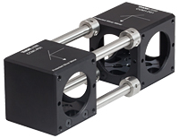
A bottom-located 8-32 (M4) tapped hole is included for post mounting. The entrance and exit ports feature our SM1 (1.035"-40) threading for compatibility with Thorlabs' SM1 lens tubes (as seen in Figure 1.1) and four 4-40 taps that accept our Ø6 mm cage rods. The mounted turning mirrors can be connected to other cage cubes through the use of our cage rods and ERSCB adapters, as shown in Figure 1.2. Please note that two turning mirrors cannot be connected using the CM1-CC Cage Cube Connector (available below) due to a lack of Ø6 mm cage rod holes on two sides of the cube. However, the CM1-CC can be used to attach the turning mirrors to other CM1 style cubes. Each mirror is epoxied within the cage cube and cannot be removed. However, empty 30 mm cage cubes are available below that are compatible with our line of unmounted Prism Mirrors. For a complete selection of our cube-mounted optics please see the Mounted Optics Guide tab.
| Item # | CCM1-F01(/M) | CCM1-G01(/M) | CCM1-P01(/M) | CCM1-M01(/M) | CCM1-E02(/M) | CCM1-E03(/M) | CCM1-K13(/M) |
|---|---|---|---|---|---|---|---|
| Unmounted Prism Item # | MRA25-F01 | MRA25-G01 | MRA25-P01 | MRA25-M01 | MRA25-E02 | MRA25-E03 | MRA25-K13 |
| Reflective Coating | UV-Enhanced Aluminum | Protected Aluminum | Protected Silver | Protected Gold | E02 Dielectric | E03 Dielectric | Nd:YAG Dielectric |
| Reflectance (Wavelength Range) |
Ravg > 90% (250 - 450 nm) |
Ravg > 90% (450 nm - 2 μm) Ravg > 95% (2 - 20 μm) |
Ravg > 97% (450 nm - 2 μm) Ravg > 95% (2 - 20 μm) |
Ravg > 96% (800 nm - 20 μm) |
Ravg > 99% (400 - 750 nm) |
Ravg > 99% (750 - 1100 nm) |
Rs and Rp: >98% (532 nm) >99% (1064 nm) |
Metallic-Coated Mirrors
| Item # | CCM1-F01(/M) | CCM1-G01(/M) | CCM1-P01(/M) | CCM1-M01(/M) |
|---|---|---|---|---|
| Unmounted Prism Item # | MRA25-F01 | MRA25-G01 | MRA25-P01 | MRA25-M01 |
| Reflective Coating | UV-Enhanced Aluminum | Protected Aluminum | Protected Silver | Protected Gold |
| Reflectance (Wavelength Range) |
Ravg > 90% (250 - 450 nm) | Ravg > 90% (450 nm - 2 μm) Ravg > 95% (2 - 20 μm) |
Ravg > 97% (450 nm - 2 μm) Ravg > 95% (2 - 20 μm) |
Ravg > 96% (800 nm - 20 μm) |
| Ports | 2 Ports, Each with SM1 (1.035"-40) Threading and Four 4-40 Taps for Cage Rods | |||
| Post Mounting | 8-32 (M4) Tapped Hole | |||
| Mirror Substrate | N-BK7a | |||
| Housing Material | Engraved Black Anodized Aluminum Housing | |||
| Surface Flatness (@ 633 nm) | <λ/10 Over Clear Aperture (Peak to Valley) | |||
| Clear Aperture | >Ø17.5 mm | |||
| Surface Quality | 40-20 Scratch-Dig | |||
| Beam Path Deviation | 90° ± 20 arcmin | |||
Dielectric-Coated Mirrors
| Item # | CCM1-E02(/M) | CCM1-E03(/M) | CCM1-K13(/M) |
|---|---|---|---|
| Unmounted Prism Item # | MRA25-E02 | MRA25-E03 | MRA25-K13 |
| Reflective Coating | E02 Dielectric | E03 Dielectric | Nd:YAG Dielectric |
| Reflectance (Wavelength Range) |
Ravg > 99% (400 - 750 nm) | Ravg > 99% (750 - 1100 nm) | Rs and Rp: >98% (532 nm) >99% (1064 nm) |
| Ports | 2 Ports, Each with SM1 (1.035"-40) Threading and Four 4-40 Taps for Cage Rods | ||
| Post Mounting | 8-32 (M4) Tapped Hole | ||
| Mirror Substrate | N-BK7a | ||
| Housing Material | Engraved Black Anodized Aluminum Housing | ||
| Surface Flatness (@ 633 nm) | <λ/10 Over Clear Aperture (Peak to Valley) | ||
| Clear Aperture | >Ø17.5 mm | ||
| Surface Quality | 10-5 Scratch-Dig | ||
| Beam Path Deviation | 90° ± 20 arcmin | ||
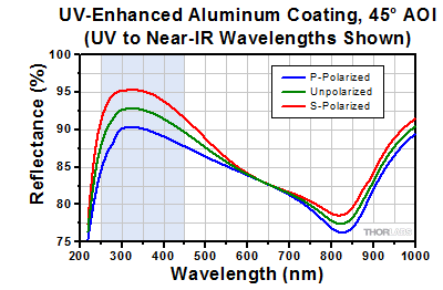
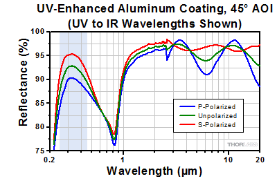
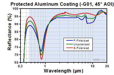
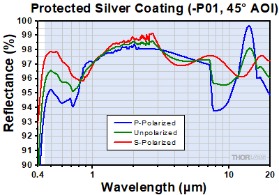
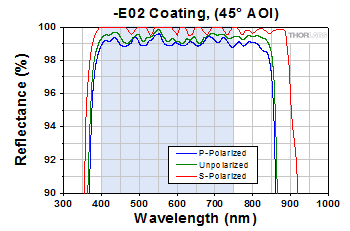
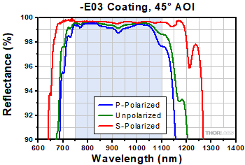
The shaded regions in the graphs denote the ranges over which we guarantee the specified reflectance. Please note that the reflectance outside of these bands is typical and can vary from lot to lot, especially in out-of-band regions where the reflectance is fluctuating or sloped.
UV-Enhanced Aluminum Coating (250 - 450 nm)
Protected Aluminum Coating (450 nm - 20 µm)
Protected Silver Coating (450 nm - 20 µm)
Protected Gold Coating (800 nm - 20 µm)
These plots show the reflectance of our -E02 (400 - 750 nm) and -E03 (750 - 1100 nm) dielectric coatings for a typical coating run. The shaded region in each graph denotes the spectral range over which the coating is highly reflective. Due to variations in each run, this recommended spectral range is narrower than the actual range over which the optic will be highly reflective. If you have any concerns about the interpretation of this data, please contact Tech Support. For applications that require a mirror that bridges the spectral range between the dielectric coatings, please consider a metallic mirror.
-E02 Coating (400 - 750 nm)
Excel Spreadsheet with Raw Data for -E02 Coating, 8° and 45° AOI
-E03 Coating (750 - 1100 nm)
Excel Spreadsheet with Raw Data for -E03 Coating, 6° and 45° AOI
-K13 Coating (532 nm and 1064 nm)
These plots show the reflectance of our Nd:YAG (532 nm and 1064 nm) dielectric coating for a typical coating run. Although there will be variations in the broadband reflectance from run to run, this optic is guaranteed to meet the reflectance specification at 532 nm and 1064 nm (see the table on the Overview tab). If you have any concerns about the interpretation of this data, please contact Tech Support.
Thorlabs offers a wide selection of optics optimized for use with Nd:YAG lasers. Please see below for more information.
30 mm Cage-Cube-Mounted Optics Selection Guide
The table below provides links to all of our 30 mm Cage-Cube-Mounted optics. For our selection of 16 mm Cage-Cube-Mounted Optics, please see our 16 mm Cage Systems guide.
30 mm Cage Cube Empty Optic Mounts Selection Guide
 | 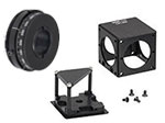 |
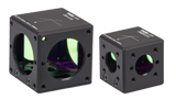
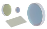
| Rectangular Dichroic Mirrors and Filters | Empty Compact 30 mm Cage Cube |
| Posted Comments: | |
Chris Niemann
(posted 2024-08-01 18:13:02.467) What is the damage threshold of these 1064/532 nm dielectric mirrors? jdelia
(posted 2024-08-02 10:16:58.0) Thank you for contacting Thorlabs. We specify the following pulsed damage thresholds for our -K13 coated mirrors: 8 J/cm^2 (532 nm, Ø0.491 mm, 10 ns, 10 Hz), 5 J/cm^2 (1064 nm, Ø1.010 mm, 10 ns, 10 Hz). Seon Seungkyu
(posted 2022-12-05 16:46:46.237) Does the CCM1-E02 product include a mirror?
Or do I have to purchase it separately? jdelia
(posted 2022-12-05 03:11:57.0) Thank you for contacting Thorlabs. Yes, the CCM1-E02 includes a MRA25-E02 prism mirror. akuznetsov
(posted 2017-11-29 14:31:54.08) Light leakage from the cubes is the only bad thing about them that I can recall. I have used tape in the past like you suggest but it should be forbidden to use tape in hardware projects. Glue ages, dries out and leaves residue and dust when pealed or it can peel off by itself as it dries out. These holes need to be fixed!
There are threads and peg positions that allow light to escape, please fix! nbayconich
(posted 2017-12-28 04:11:49.0) Thank you for your feedback. I have forwarded your request to our research and design team for future consideration. I will contact you directly about our custom capabilities. mtaormin
(posted 2015-04-01 15:07:41.833) Sometimes I need to make a compact periscope (that may include a right angle turn) and it would be great to use CM1-CC to connect two CM1-E02. The hole patterns, both for the dowels and the screws make this impossible, however. I think you should consider tapped holes on all faces of the turning mirror cubes. cdaly
(posted 2015-04-15 10:27:49.0) Response from Chris at Thorlabs: At the moment, the CM1-CC is not compatible with two of the cube mounted turning prisms due to the lack of 30 mm cage system holes on two sides. We will discuss internally the possibility of implementing a change in the future for the inclusion of these holes, but for now, two of these cubes can be connected using 4 each of ER025 and ERSCA. ted
(posted 2013-11-06 01:38:02.91) Hi,
I'm on this page:
http://www.thorlabs.de/newgrouppage9.cfm?objectgroup_id=1670
trying to figure out which cage-mounted mirror to get, but the overview table listing the various options is incorrect - and confusing. For each cube there is a link to the item # of the prism that is mounted in it, but these are clearly not the right items; silver alu mirror in the silver mirrored cube etc.
Regards,
Thomas lmorgus
(posted 2013-11-08 05:44:40.0) Response from Laurie at Thorlabs to Ted: Thank you for taking the time to point out an error on our website. We have updated the table to reflect the correct information. user
(posted 2013-09-06 20:28:25.4) Unfortunately, the light tightness of the CM1 cubes was lost due to alignment holes near the SM1-thread. cdaly
(posted 2013-09-11 17:57:00.0) Response from Chris at Thorlabs: Thank you for your feedback. This can be made light tight by covering the alignment holes with blackout tape like T743-2.0. I agree, it would be nice to have the hole not go all the way through the side face to maintain this property without having to use tape. I will discuss this with our engineers and perhaps we can have the part modified with your suggestion. tcohen
(posted 2012-07-10 12:21:00.0) Response from Tim at Thorlabs: To mount a 1” diameter 1mm thick optic into a cage compatible cube such as the C6W we offer the part B5C. This can be mounted onto a rotation platform such as the B3C to alter the AOI. All of these parts can be found at http://www.thorlabs.com/NewGroupPage9.cfm?ObjectGroup_ID=3929. As a side note, an OD of .1 gives us ~80% T (10^-OD) and with a typical value of ~10% R (both slightly wavelength dependent) for our ND01B, the beamsplitting may be closer to 8:1. I have contacted you to go through our options with you to help determine the best solution. kvasnicka
(posted 2012-07-10 08:00:46.0) Hi, is there a way to mount a 1" diameter, 1 mm thickness optic into the cube (CM1-4ER/M or other) at 45 degrees? I want to use an O.D. 1 reflective filter as a 1:10 beamsplitter, but these filters I only found circular at ThorLabs. Thorlabs
(posted 2010-08-03 13:08:33.0) Response from Javier at Thorlabs to Paul: Thank you for your update. I will take a look at our stock parts and evaluate them based on your input. paulwb.at.work
(posted 2010-08-02 20:09:24.0) Hi Javier, an update on the interference issue. I hadnt mounted actual beamsplitter cubes in the clamps until today, and the top plate of the cube clamp (the triangular section with felt on the underside) appears to have interference issues with the small ER screws. I have only tested this with one cube, but Im going to take a file to the other clamps just in case. Judging by the depth of the gouge left after my (a tad forceful--ahem) attempt at insertion, it should be a matter of a few strokes of the file. Thorlabs
(posted 2010-07-22 08:49:08.0) Response from Javier at Thorlabs to paul.at.work: Thank you for your feedback. We are discussing adding these changes to the CM1-4ER reusable cube internally. Having access to the three internal screws that hold the optic without having to dissasemble the mount is definitely an advantage, so we will look into adding clearance holes on the top of the cube. We will also investigate your second concern. I will keep you updated about any changes. paulwb.at.work
(posted 2010-07-21 15:32:10.0) Concerning the CM1-4ER.
I understand that some people need this cube to be light tight in different ways, but adding three holes in the top shell, giving access to the three cube holder screws, would allow the glass cube to be freed and adjusted manually from the side holes, without having to disassemble the rest of the cage mount setup. Drilling these out was not fun.
Also, I had to file down the four corners on the base plate as the small screws that the cage mount ER rods use caused interference when putting the top shell and the base plate together. 15 seconds with a coarse file was all that was needed per corner, but it still was tedious to do 9+ cubes. clin
(posted 2007-07-27 17:14:13.0) KCB1 is hiding on the bottom and we should add a pic or application idea on top!
( like the pic on related parts on this link, http://www.thorlabs.com/product.cfm?ObjectGroup_ID=2856&pn=KC1 ) |

Click to Enlarge
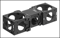
Figure 437B A C4W and C6W Cage Cube connected to a 1.5" wide
CCM1-4ER Compact Cage Cube using the C4W-CC and CM1-CC Cube Connectors, respectively.
Click to Enlarge
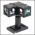
Figure 437A CM1-CC Cage Cube Connector Connecting Multiple 1.5" Wide Cage Cubes
- Connect Two 1.5" Wide Cage Cubes Side by Side
- Connect a 1.5" Wide Cage Cube to a 2" Wide Cage Cube
- Compatible with CM1 or CCM1 Series Cage Cubes
The CM1-CC cage cube connector allows two or more CM1 or CCM1 style cubes to be connected as shown in Figure 437A. The CM1 and CCM1 series of cage cubes, which are all compatible with this connector, include empty cubes, empty dichroic cubes, mounted beamsplitters, mounted penta prisms, and mounted turning mirrors. The CM1-CC cage cube connector includes four 4-40 button-head screws, two 4-40 flat-head screws, four washers, and a 1/16" hex key.
Two cage cube-mounted turning mirrors cannot be connected using the CM1-CC due to a lack of Ø6 mm cage rod holes on two sides of the cube.
We also offer the C4W-CC to connect two 2" wide 30 mm cage cubes. Both C4W-CC and CM1-CC cage cube connectors can be used to connect one 1.5" wide 30 mm cage cube, such as our CCM1-4ER(/M), with a 2" wide 30 mm cage cube.
Alignment Pins
Please note that because dowel alignment pins are used, the connector requires drilled holes on the cube face between the SM1-threaded (1.035"-40) ports. If you have an older cube and would like it updated to have alignment holes for free, please contact Technical Support. Alternatively, the alignment pins are press-fit inside their mounting holes, and can be pressed out for use with cubes that do not have these alignment holes.

Click to Enlarge
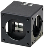
Figure 308B BS127CAM Beamsplitter Cube Adapter Mounted in the CCM1-4ER Cage Cube (Optic and Adapter Sold Separately)
Click to Enlarge
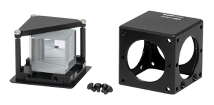
Figure 308A CCM1-4ER with Penta Prism (Optic Sold Separately)
- Compatible with 30 mm Cage System and SM1 Lens Tubes
- Directly Accepts 1" Cubes and 25 mm Right-Angle Prisms
- Mounting Adapters Available for Thorlabs' Beamsplitter Cubes Smaller than 25 mm
- Four SM1-Threaded Ports
- Base is Post Mountable via 8-32 (M4) Tap
- 3 Prism Alignment Stops Provide Accuracy of ±20 arcmin
These 1.5" wide cage cubes directly accept a 1" or 25 mm square optic, such as a beamsplitter cube or right-angle prism, with adapters available here for mounting a 5 mm (0.20"), 10 mm (0.39"), 12.7 mm (0.50"), or 20 mm (0.79") beamsplitter cube. The base of the cube has an 8-32 (M4) tap to attach to Ø1/2" Posts. Shown in Figure 308B is a 12.7 mm (0.50") beamsplitter cube being mounted in the CCM1-4ER using the BS127CAM Beamsplitter Cube Adapter. Two cage cubes can be connected using ER rods and
The optic is clamped within the cube by tightening three 1.5 mm hex screws of a tension plate (see Figure 308A), allowing the user to replace the optic with any other compatible optic when necessary. The optic must sit flush against the three corners of the cube base. Do not overtighten the tension plate, this could damage the optic. Figure 308A shows a penta prism mounted in a CCM1-4ER with the outer housing removed.
 Products Home




_45deg_G1-350.gif) Click to Enlarge
Click to Enlarge_0deg_G1-350.gif) Click to Enlarge
Click to Enlarge_45deg_G1-350.gif) Click to Enlarge
Click to Enlarge_0deg_G1-350.gif) Click to Enlarge
Click to Enlarge





 Zoom
Zoom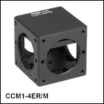
 30 mm Cage Cube-Mounted Turning Prism Mirrors