 Products Home / Optomechanical Components / Optical Post Assemblies / Bases / Table Clamps / Pin-Aligned, Clamping Post Bases
Pin-Aligned, Clamping Post Bases
- Positions the Reflective Surface of an Optic Above a Hole in an Optical Table to Simplify Alignment
- Designed for Mounts with a Post-Centered Reflective Optical Surface or KCB Series Mounts (Except KCB1P(/M))
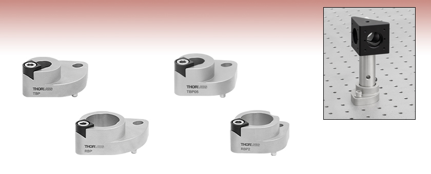
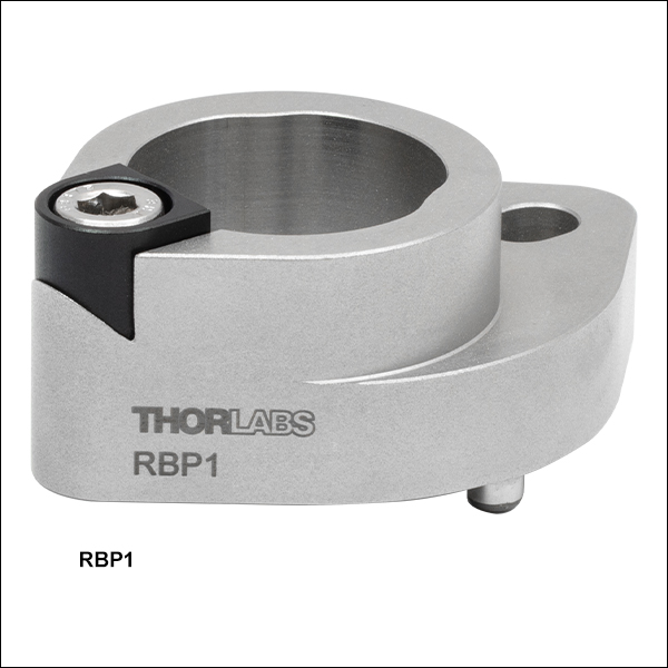
RBP
For Mounts with a Post-Centered Reflective Optical Surface Mounted on Ø1" Pillar Posts
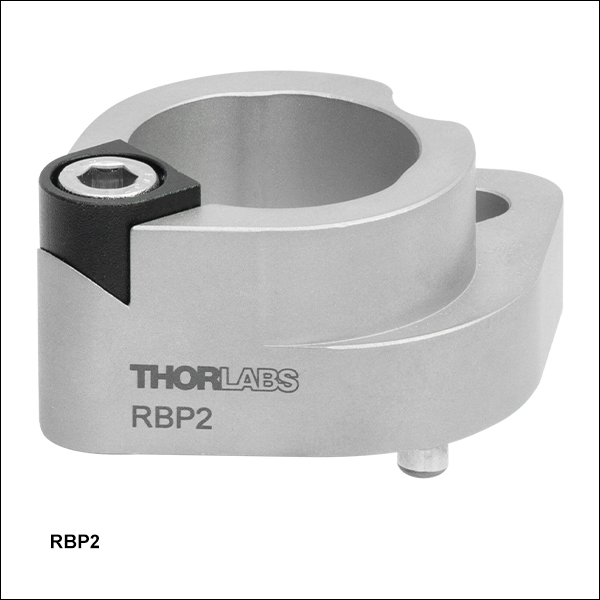
RBP2
For KCB2 Series Mounts Mounted on Ø1" Pillar Posts
Application Idea
The RBP1 Post Base positions the reflective surface of an optic in a KCB1 Mount on a Ø1" RS Post above a threaded hole in an optical table.
TBP
For Mounts with a Post-Centered Reflective Optical Surface Mounted on
Ø1/2" Pillar Posts
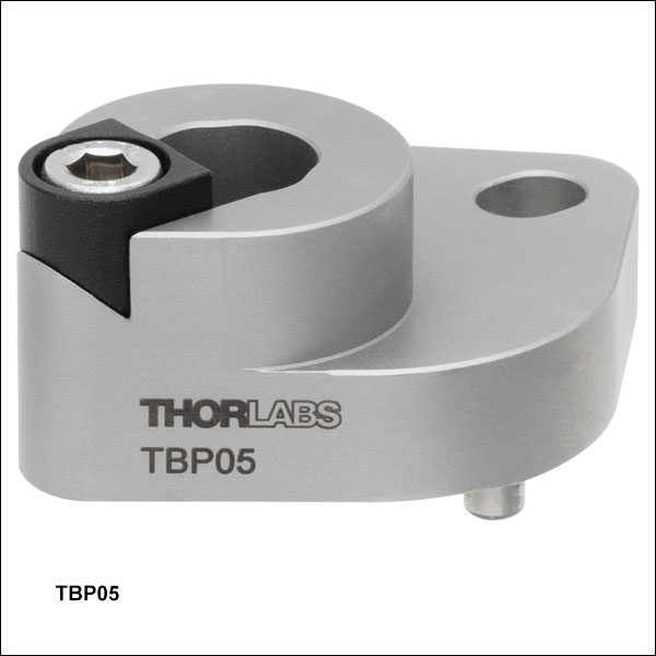
TBP05
For KCB05 Series Mounts on Ø1/2" Pillar Posts


Please Wait

Click to Enlarge A BHM6 ruler is used with RBP1 and RBP post bases to align a Mach-Zehnder interferometer using KCB1 mirror mounts and CCM1-PBS251 cage cube-mounted polarizing beamsplitter cubes.

Click to Enlarge
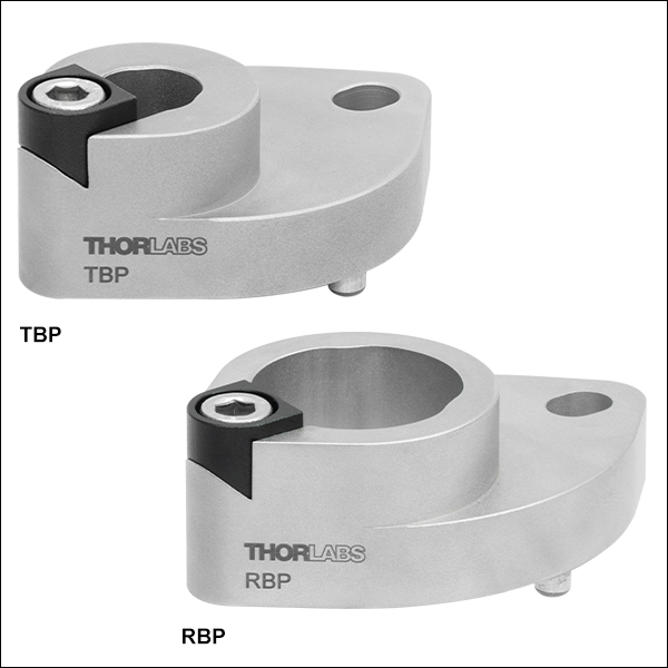
Top and Bottom View of the RBP1 Post Base
Features
- Ideal for Positioning an Optical Path Along the Threaded Holes of an Optical Table
- Compatible with Imperial and Metric Optical Tables
- Options for Ø12 mm, Ø1/2" (Ø12.7 mm), or Ø1" (Ø25 mm) Optical Posts
- Alignment Pins Position the Reflective Surface of an Optic in a Compatible Mount Above a Hole in the Table
- TBP(/M), RBP(/M), and TBP/M-JP: Compatible with Mounts with a Post-Centered Reflective Optical Surface
- TBP05(/M) and TBP05/M-JP: Compatible with KCB05 Series Mounts
- RBP1(/M): Compatible with KCB1 Series Mounts (Except KCB1P(/M))
- RBP2(/M): Compatible with KCB2 Series Mounts
- Post Rotates Freely When Locking Screw is Loosened
Thorlabs' Pin-Aligned, Clamping Post Bases are designed to simplify positioning an optical path over the threaded holes in an imperial or metric optical table by holding the reflective surface of a mirror or other reflective optic mounted in a compatible mount above a hole in the table. The TBP(/M), RBP(/M), and TBP/M-JP bases are designed to be used with kinematic or cube mounts that center the reflective surface of a mounted optic above the hole in an optical post. The TBP05(/M) and TBP05/M-JP bases are compatible with KCB05 Series Right-Angle Kinematic Mounts. The RBP1(/M) bases work with KCB1 Series Right-Angle Kinematic Mounts (except Item # KCB1P(/M)). RBP2(/M) bases are compatible with KCB2 Series Right-Angle Kinematic Mounts.
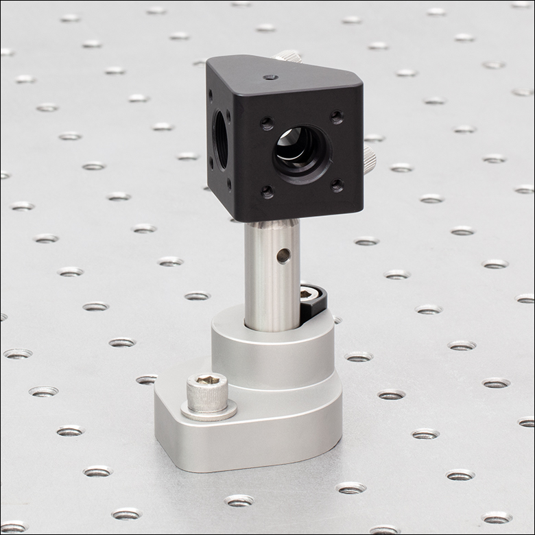
Click to Enlarge Using an TBP05 Post Base and KCB05 Mount to Position an Optical Path Above the Threaded Holes in an Optical Table
The TBP(/M) and TBP05(/M) post bases accept Ø1/2" (Ø12.7 mm) Optical Posts, such as our TR Posts, as shown in the image to the left. The TBP/M-JP and TBP05/M-JP post bases accept Ø12 mm Posts. The RBP(/M), RBP1(/M), and RBP2(/M) post bases accept Ø1" (Ø25 mm) Posts, such as our RS Pillar Posts. Note that the bases do not accept pedestal posts. Alignment pins on the bottom of these post bases fit into the holes on an optical table with a 1" (25 mm) grid spacing, which sets the mount in the correct position, and a 1/4"-20 (M6 x 1.0) cap screw and washer (not included) can be used to secure the post base to the table. The body of the post base is made of stainless steel, with an anodized aluminum piece that works with the locking screw to lock the post to the clamp.
Once the pin-aligned, clamping post base is attached to the table, the post can be placed in the base and rotated into position. Once the desired rotation is reached, the post can be locked into place by tightening the locking screw with a 3/16" (5 mm) hex key or balldriver. The post clamping mechanism uses three points of contact for stable mounting (see the image to the near upper right). We recommend the BHM6 Magnetic Beam Height Ruler with Dowel Pins as an ideal tool for aligning a laser with a table's hole pattern using the pin-aligned, clamping post bases, as it places a series of alignment holes at different heights above two threaded holes in the table (see the image to the upper right). Please see the Insights tab for more details on alignment of laser beams with an optical table's threaded holes.

Insights into Aligning a Laser Beam
When installing a laser in an optical setup, it is good practice to start by leveling and orienting its beam so that it travels along a well-defined path. When the beam is prepared this way, not only is it easier to then divert the beam and route it through the optical elements in the system, but the results provided by tuning the system's alignment are more predictable and repeatable. The following sections describe how to:
- Level and Align the Laser Beam's Pointing Angle
- Divert the Beam and Align it to Follow a Desired Path
Click here for more Insights about lab practices and equipment.
Level and Align the Laser Beam's Pointing Angle
0:00 - Introduction
1:25 - Level and Align the Laser Beam's Pointing Angle
4:09 - Divert the Beam and Align it to Follow a Desired Path

Click to Enlarge
Figure 2: The beam can be aligned to travel parallel to a line of tapped holes in the optical table. The yaw adjustment on the kinematic mount adjusts the beam angle, so that the beam remains incident on the ruler's vertical reference line as the ruler slides along the line of tapped holes.

Click to Enlarge
Figure 1: Leveling the beam path with respect to the surface of an optical table requires using the pitch adjustment on the kinematic laser mount (Figure 2). The beam is parallel to the table's surface when measurements of the beam height near to (left) and far from (right) the laser's front face are equal.
Pitch (tip) and yaw (tilt) adjustments provided by a kinematic mount can be used to make fine corrections to a laser beam's angular orientation or pointing angle. This angular tuning capability is convenient when aligning a collimated laser beam to be level with respect to a reference plane, such as the surface of an optical table, and when aligning with respect to a particular direction in that plane, such as along a line of tapped holes in the table.
Before Using the Mount's Adjusters
First, rotate each adjuster on the kinematic mount to the middle of its travel range. This reduces the risk of running out of adjustment range, and the positioning stability is frequently better when at the center of an adjuster's travel range.
Then, make coarse corrections to the laser's height, position, and orientation. This can be done by adjusting the optomechanical components, such as a post and post holder, supporting the laser. Ensure all locking screws are tightened after the adjustments are complete.
Level the Beam Parallel to the Table's Surface
Leveling the laser beam is an iterative process that requires an alignment tool and the fine control provided by the mount's pitch adjuster.
Begin each iteration by measuring the height of the beam close to and far from the laser (Figure 1). A larger distance between the two measurements increases accuracy. If the beam height at the two locations differs, place the ruler in the more distant position. Adjust the pitch on the kinematic mount until the beam height at that location matches the height measured close to the laser. Iterate until the beam height at both positions is the same.
More than one iteration is necessary, because adjusting the pitch of the laser mount adjusts the height of the laser emitter. In the video for example, the beam height close to the laser was initially 82 mm, but it increased to 83 mm after the pitch was adjusted during the first iteration.
If the leveled beam is at an inconvenient height, the optomechanical components supporting the laser can be adjusted to change its height. Alternatively, two steering mirrors can be placed after the laser and aligned using a different procedure, which is detailed in the section. Steering mirrors are particularly useful for adjusting beam height and orientation of a fixed laser.
Orient the Beam Along a Row of Tapped Holes
Aligning the beam parallel to a row of tapped holes in the table is another iterative process, which requires an alignment tool and tuning of the mount's yaw adjuster.
The alignment tool is needed to translate the reference line provided by the tapped holes into the plane of the laser beam. The ruler can serve as this tool, when an edge on the ruler's base is aligned with the edges of the tapped holes that define the line (Figure 2).
The relative position of the beam with respect to the reference line on the table can be evaluated by judging the distance between the laser spot and vertical reference feature on the ruler. Vertical features on this ruler include its edges, as well as the columns formed by different-length rulings. If these features are not sufficient and rulings are required, a horizontally oriented ruler can be attached using a BHMA1 mounting bracket.
In the video, when the ruler was aligned to the tapped holes and positioned close to the laser, the beam's edge and the ends of the 1 mm rulings coincided. When the ruler was moved to a farther point on the reference line, the beam's position on the ruler was horizontally shifted. With the ruler at that distant position, the yaw adjustment on the mount was tuned until the beam's edge again coincided with the 1 mm rulings. The ruler was then moved closer to the laser to observe the effect of adjusting the mount on the beam's position. This was iterated as necessary.
Divert the Beam and Align it to Follow a Desired Path
The first steering mirror reflects the beam along a line that crosses the new beam path. A second steering mirror is needed to level the beam and align it along the new path. The procedure of aligning a laser beam with two steering mirrors is sometimes described as walking the beam, and the result can be referred to as a folded beam path. In the example shown in the video above, two irises are used to align the beam to the new path, which is parallel to the surface of the optical table and follows a row of tapped holes.
Click to Enlarge
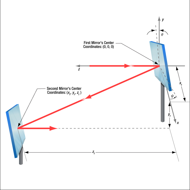
Figure 3: The beam reflected from Mirror 1 will be incident on Mirror 2, if Mirror 1 is rotated around the x- and y-axes by angles θ and ψ, respectively. Both angles affect each coordinate (x2 , y2 , z2 ) of Mirror 2's center. Mirror 1's rotation around the x-axis is limited by the travel range of the mount's pitch (tip) adjuster, which limits Mirror 2's position and height options.

Click to Enlarge
Figure 5: The adjusters on the second kinematic mirror are used to align the beam on the second iris.

Click to Enlarge
Figure 4: The adjusters on the first kinematic mirror mount are tuned to position the laser spot on the aperture of the first iris.
Setting the Heights of the Mirrors
The center of the first mirror should match the height of the input beam path, since the first mirror diverts the beam from this path and relays it to a point on the second mirror. The center of the second mirror should be set at the height of the new beam path.
Iris Setup
The new beam path is defined by the irises, which in the video have matching heights to ensure the path is level with respect to the surface of the table. A ruler or calipers can be used to set the height of the irises in their mounts with modest precision.
When an iris is closed, its aperture may not be perfectly centered. Because of this, switching the side of the iris that faces the beam can cause the position of the aperture to shift. It is good practice to choose one side of the iris to face the beam and then maintain that orientation during setup and use.
Component Placement and Coarse Alignment
Start by rotating the adjusters on both mirrors to the middle of their travel ranges. Place the first mirror in the input beam path, and determine a position for the second mirror in the new beam path (Figure 3). The options are notably restricted by the travel range of the first mirror mount's pitch (tip) actuator, since it limits the mirror's rotation (θ ) around its x-axis. In addition to the pitch, the yaw (tilt) of the first mirror must also be considered when choosing a position
After placing the second mirror on the new beam path, position both irises after the second mirror on the desired beam path. Locate the first iris near the second mirror and the second iris as far away as possible.
While maintaining the two mirrors' heights and without touching the yaw adjusters, rotate the first mirror to direct the beam towards the second mirror. Adjust the pitch adjuster on the first mirror to place the laser spot near the center of the second mirror. Then, rotate the second mirror to direct the beam roughly along the new beam path.
First Hit a Point on the Path, then Orient
The first mirror is used to steer the beam to the point on the second mirror that is in line with the new beam path. To do this, tune the first mirror's adjusters while watching the position of the laser spot on the first iris (Figure 4). The first step is complete when the laser spot is centered on the iris' aperture.
The second mirror is used to steer the beam into alignment with the new beam path. Tune the adjusters on the second mirror to move the laser spot over the second iris' aperture (Figure 5). The pitch adjuster levels the beam, and the yaw adjuster shifts it laterally. If the laser spot disappears from the second iris, it is because the laser spot on the second mirror has moved away from the new beam path.
Tune the first mirror's adjusters to reposition the beam on the second mirror so that the laser spot is centered on the first iris' aperture. Resume tuning the adjusters on the second mirror to direct the laser spot over the aperture on the second iris. Iterate until the laser beam passes directly through the center of both irises, as shown in the video. If any adjuster reaches, or approaches, a limit of its travel range, one or both mirrors should be repositioned and the alignment process repeated.
If a yaw axis adjuster has approached a limit, note the required direction of the reflected beam and then rotate the yaw adjuster to the center of its travel range. Turn the mirror in its mount until the direction of the reflected beam is approximately correct. If the mirror cannot be rotated, reposition one or both mirrors to direct the beam roughly along the desired path. Repeat the alignment procedure to finely tune the beam's orientation.
If a pitch axis adjuster has approached a limit, either increase the two mirrors' separation or reduce the height difference between the new and incident beam paths. Both options will result in the pitch adjuster being positioned closer to the center of its travel range after the alignment procedure is repeated.
| Posted Comments: | |
| No Comments Posted |

 Zoom
Zoom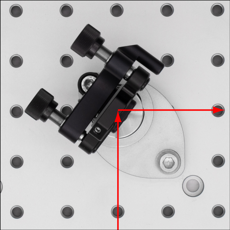
Click to Enlarge Alignment of Laser Beam Along Holes of an Optical Table Using an RBP Post Base
| Compatible Mounts for the TBP(/M), RBP(/M), and TBP/M-JP Bases | |
|---|---|
| Kinematic Mirror Mounts: KM05CP(/M), KM100CP(/M), and KM200CP(/M) |
|
| Kinematic Mirror Mounts with Centering Plates: KM05(/M) with KCP05(/M), KM100 with KCP1(/M), and KM200 with KCP2(/M) |
|
| 16 mm Cage Cubes, 30 mm Cage Cubes, and 60 mm Cage Cubes with Centered 8-32 (M4 x 0.7) or 1/4"-20 (M6 x 1.0) Mounting Holes |
|
- Compatible with Mounts with a Post-Centered Reflective Optical Surface
- Positions the Reflective Surface of an Optic in a Compatible Mount Above a Hole in an Optical Table
- Ideal for Aligning a Laser Beam Along the Threaded Holes of an Optical Table
- Compatible with Imperial and Metric Optical Tables with Options for Ø12 mm, Ø1/2" (Ø12.7 mm), or Ø1" (Ø25 mm) Pillar Posts
These Pin-Aligned, Clamping Post Bases are designed to work with mounts that center the reflective surface of an optic above an optical post (please see the table to the right for compatible mounts). The pins on the bottom of the post bases fit into the holes of an optical table with a 1" (25 mm) grid spacing, and each base can be secured in position with a 1/4"-20 (M6 x 1.0) cap screw and washer (not included). The TBP(/M) post base accepts a Ø1/2" (Ø12.7 mm) pillar post, the RBP(/M) post base accepts a Ø1" (Ø25 mm) pillar post, and the TBP/M-JP post base accepts a Ø12 mm pillar post. The post can rotate freely until the locking screw is tightened using a 3/16" (5 mm) hex key (see the Overview tab for details).
These post bases are designed such that when a post attached to a compatible mount is placed into the base, the reflective surface of the optic is positioned above a threaded hole in the optical table (see image to the right). Tightening the locking screw securely holds the post in position.

 Zoom
Zoom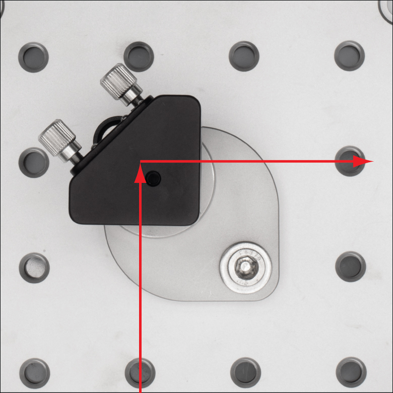
Click to Enlarge Alignment of Laser Beam Along Holes of an Optical Table Using an TBP05 Post Base
- Compatible with KCB05(/M), KCB05C(/M),or KCB05E(/M) Right-Angle Kinematic Mirror Mounts
- Positions the Front Surface of a Reflective Optic in a Compatible Mount Above a Hole in an Optical Table
- Ideal for Aligning a Laser Beam Along the Threaded Holes of an Optical Table
- Compatible with Imperial and Metric Optical Tables with Options for Ø12 mm or Ø1/2" (Ø12.7 mm) Pillar Posts
The TBP05(/M) and TBP05/M-JP Pin-Aligned, Clamping Post Bases are designed to work with mounts that center the reflective surface of an optic above an optical post. The pins on the bottom of the post bases fit into the holes of an optical table with a 1" (25 mm) grid spacing, and each base can be secured in position with a 1/4"-20 (M6 x 1.0) cap screw and washer (not included). The TBP05(/M) and TBP05/M-JP Pin-Aligned, Clamping Post Bases are designed to work with KCB05(/M), KCB05C(/M), or KCB05E(/M) Right-Angle Kinematic Mirror Mounts. The TBP05(/M) post base accepts Ø1/2" (Ø12.7 mm) pillar post, and the TBP05/M-JP post base accepts a Ø12 mm pillar post. The post can rotate freely until the locking screw is tightened using a 3/16" (5 mm) hex key (see the Overview tab for details).
These post bases are designed such that when a post attached to a compatible mount is placed into the base and the mount is oriented with the back of the mirror mount above the anodized locking mechanism, the front surface of the optic is positioned above a threaded hole in the optical table (see image to the right). Tightening the locking screw securely holds the post in position.
)")
 Zoom
Zoom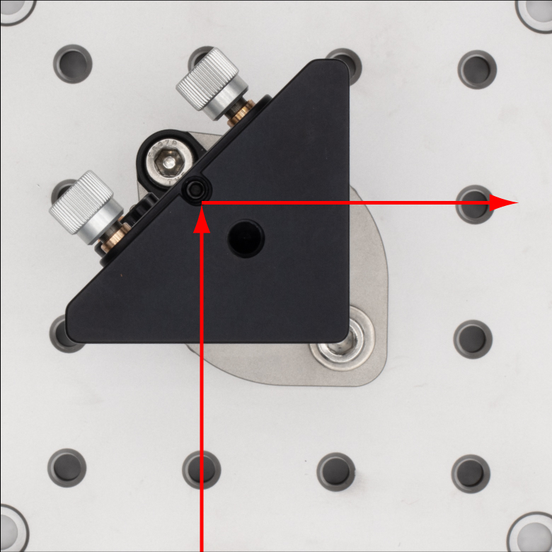
Click to Enlarge Alignment of Laser Beam Along Holes of an Optical Table Using an RBP1 Post Base
- Compatible with KCB1(/M), KCB1C(/M), KCB1E(/M), or KCB1EC(/M) Right-Angle Kinematic Mirror Mounts
- Positions the Front Surface of a Reflective Optic in a Compatible Mount Above a Hole in an Optical Table
- Ideal for Aligning a Laser Beam Along the Threaded Holes of an Optical Table
- Compatible with Imperial and Metric Optical Tables and Ø1" (Ø25 mm) Pillar Posts
The RBP1(/M) Pin-Aligned, Clamping Post Base is designed to work with mounts that center the reflective surface of an optic above an optical post. The pins on the bottom of the post base fit into the holes of an optical table with a 1" (25 mm) grid spacing, and the base can be secured in position with a 1/4"-20 (M6 x 1.0) cap screw and washer (not included). The RBP1(/M) Pin-Aligned, Clamping Post Base is designed to work with a KCB1(/M), KCB1C(/M), KCB1E(/M), or KCB1EC(/M) Right-Angle Kinematic Mirror Mount attached to a Ø1" (Ø25 mm) pillar post. The post can rotate freely until the locking screw is tightened using a 3/16" (5 mm) hex key (see the Overview tab for details).
The post base is designed such that when a post attached to a compatible mount is placed into the base and the mount is oriented with the back of the mirror mount above the anodized locking mechanism, the front surface of the optic is positioned above a threaded hole in the optical table (see image to the right). Tightening the locking screw securely holds the post in position.

 Zoom
Zoom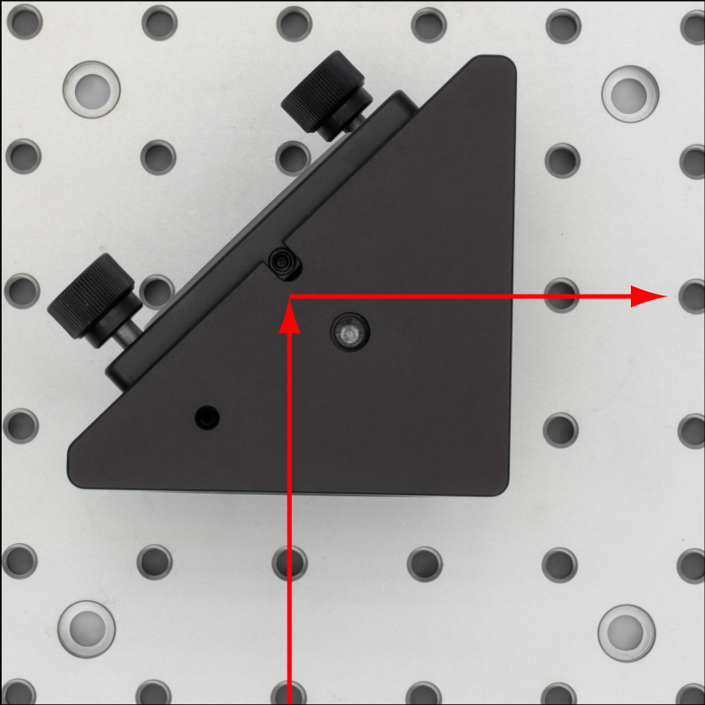
Click to Enlarge Alignment of Laser Beam Along Holes of an Optical Table Using an RBP2 Post Base
- Compatible with KCB2(/M), KCB2C(/M),or KCB2EC(/M) Right-Angle Kinematic Mirror Mounts
- Positions the Front Surface of a Reflective Optic in a Compatible Mount Above a Hole in an Optical Table
- Ideal for Aligning a Laser Beam Along the Threaded Holes of an Optical Table
- Compatible with Imperial and Metric Optical Tables and Ø1" (Ø25 mm) Pillar Posts
The RBP2(/M) Pin-Aligned, Clamping Post Base is designed to work with mounts that center the reflective surface of an optic above an optical post. The pins on the bottom of the post base fit into the holes of an optical table with a 1" (25 mm) grid spacing, and the base can be secured in position with a 1/4"-20 (M6 x 1.0) cap screw and washer (not included). The RBP2(/M) Pin-Aligned, Clamping Post Base is designed to work with a KCB2(/M), KCB2C(/M), or KCB2EC(/M) Right-Angle Kinematic Mirror Mount attached to a Ø1" (Ø25 mm) pillar post. The post can rotate freely until the locking screw is tightened using a 3/16" (5 mm) hex key (see the Overview tab for details).
The post base is designed such that when a post attached to a compatible mount is placed into the base and the mount is oriented with the back of the mirror mount above the anodized locking mechanism, the front surface of the optic is positioned above a threaded hole in the optical table (see image to the right). Tightening the locking screw securely holds the post in position.