Unmounted Achromatic Doublets, AR Coated: 650 - 1050 nm
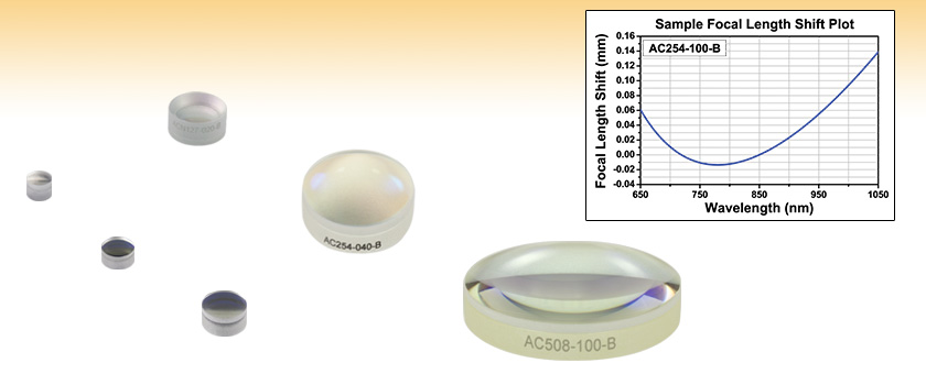
- Achromatic Performance with AR Coating for 650 - 1050 nm
- Multi-Element Design Minimizes Spot Size
- Custom Achromatic Optics Available
ACN127-020-B
f = -20 mm, Ø1/2"
AC050-008-B
f = 7.5 mm, Ø5 mm
AC060-010-B
f = 10 mm, Ø6 mm
AC080-010-B
f = 10 mm, Ø8 mm
AC254-040-B
f = 40 mm, Ø1"
AC508-100-B
f = 100 mm, Ø2"

Please Wait
| General Specifications | ||
|---|---|---|
| Design Wavelengths | 706.5 nm, 855 nm, and 1015 nm | |
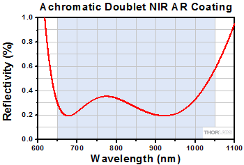
| AR Coating Range | 650 - 1050 nm | |
| Reflectance Over AR Coating Range (0° AOI) |
Ravg < 0.5% | |
| Diameters Available | 2 mm, 5 mm, 6 mm, 6.35 mm, 8 mm, 1/2", 1", 30 mm, or 2" |
|
| Diameter Tolerance | +0.0 / -0.1 mma | |
| Focal Length Tolerance | ±1%b | |
| Surface Quality | 40-20 Scratch-Digc | |
| Spherical Surface Powerd | 3λ/2 | |
| Spherical Surface Irregularity (Peak to Valley) |
λ/4 at 632.8 nm | |
| Centration | <3 arcmine | |
| Clear Aperture | >90% of Diameter | |
| Damage Thresholdf | Pulsed | 5.0 J/cm2 (810 nm, 10 ns Pulse, 10 Hz, Ø0.155 mm) |
| CWg | 1000 W/cm (1070 nm, Ø0.971 mm) | |
| Operating Temperature | -40 °C to 85 °C | |
| Achromatic Doublet Selection Guide | |
|---|---|
| Unmounted Lenses | Mounted Lenses |
| Visible (400 - 700 nm) | Visible (400 - 700 nm) |
| Extended Visible (400 - 1100 nm) | Extended Visible (400 - 1100 nm) |
| Near IR (650 - 1050 nm) | Near IR (650 - 1050 nm) |
| IR (1050 - 1700 nm) | IR (1050 - 1700 nm) |
| Achromatic Doublet Kits | |
| Click on the red Document icon next to the item numbers below to access the Zemax file download. Our entire Zemax Catalog is also available. |
Features
- AR Coated for the 650 - 1050 nm Range
- Positive Doublet Sizes from Ø2 mm to Ø2"
- Negative Doublet Sizes: Ø1/2" and Ø1"
- 4 mm to 1000 mm Focal Lengths for Positive Doublets
- -20 mm to -100 mm Focal Lengths for Negative Doublets
Thorlabs' cemented Achromatic Doublets, which are designed for use in the near IR spectral region (650 - 1050 nm), are optimized at infinite conjugate ratios. With design wavelengths at 706.5 nm, 855.0 nm, and 1015 nm, these doublets are useful for controlling chromatic and spherical aberration, offering superior performance to singlet lenses.
To see how the performance of achromatic doublets compares to single lenses, refer to the Application tab above. In addition, the Performance tab gives examples of how the performance of achromatic doublets can be analyzed by downloading the Zemax® files found by clicking the document icon next to the appropriate part number below.
For best performance, the side of the lens with the largest radius of curvature (flattest side) should face away from the collimated beam. Doublets Ø1/2" and larger are engraved with the item # on their edge, oriented so that the text is right-side up when the flattest side of the lens is the bottom surface. Please see the diagram under the reference drawing link below for additional details.
A recommended fixed lens mount is listed in the footnote under each specification table below. Alternatively, choose a mount from our selection of fixed diameter lens mounts, self-centering adjustable lens mounts, or adjustable lens mounts. When choosing a lens mount, make sure the mount can accommodate the diameter and edge thickness specifications of the lens. The Achromatic Doublets featured on this page are also available in a mounted version. For applications in wavelength regimes less than 410 nm, Thorlabs’ air-gap UV doublets provide excellent performance down to 240 nm.
In the specification tables below a positive radius of curvature indicates that the surface is opening to the right when the lens is oriented as shown in the reference drawing while a negative radius of curvature indicates that the surface is opening to the left. Both the positive and negative lenses have an infinite conjugate ratio (i.e., if a diverging light source is placed one focal length away from the flatter side of the lens, the light rays emerging from the curved side will be collimated).
Custom Achromatic Lenses
Thorlabs' optics business unit has a wide breadth of manufacturing capabilities that allow us to offer a variety of custom achromatic optics for both OEM sales and low quantity one-off orders. Achromatic optics with customer-defined sizes, focal lengths, substrate materials, cement materials, and coatings are all available as customs. In addition, we can offer optics that exceed the specifications of our stock catalog offerings. To receive more information or inquire about a custom order, please contact Tech Support.
Detailed information regarding each achromatic doublet can be found in the Zemax® files included with the support documents for each doublet. Below are some examples of how the performance of these lenses can be examined using the Zemax® files.
Focal Shift vs. Wavelength
Thorlabs' achromatic doublets are optimized to provide a nearly constant focal length across a broad bandwidth. This is accomplished by utilizing a multi-element design to minimize the chromatic aberration of the lens. Dispersion in the first (positive) element of the doublet is corrected by the second (negative) element, resulting in better broadband performance than spherical singlets or aspheric lenses. The graph below shows the paraxial focal shift as a function of wavelength for the AC254-200-B, which is a 200 mm focal length, Ø25.4 mm achromatic doublet AR coated for the 650 to 1050 nm range.

Click to Enlarge
Figure 1
Wavefront Error and Spot Size
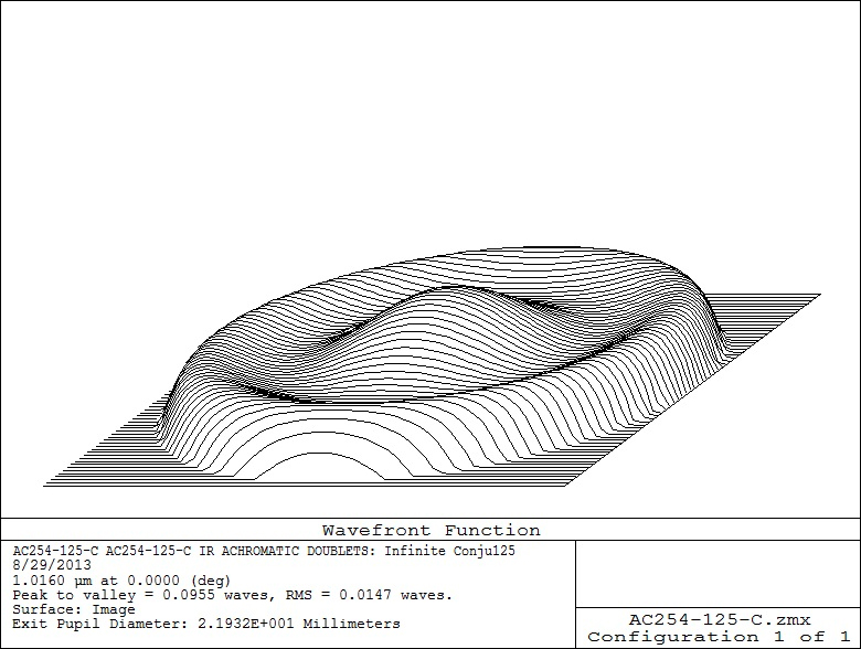
Thorlabs' spherical doublet lenses have been corrected for various aberrations, including spherical aberration, chromatic aberration, and coma. One way of displaying the theoretical level of correction is through plots of wavefront error and ray traces to determine spot size. For example, in Figure 2, a plot of wavefront at the image plane reveals information regarding aberration correction by using the AC254-200-C. In this example, the wavefront error is theoretically on the order of 3/100 of a wave. This indicates that the optical path length difference (OPD) is extremely small for arrays going through the center of the lens and at nearly full aperture.
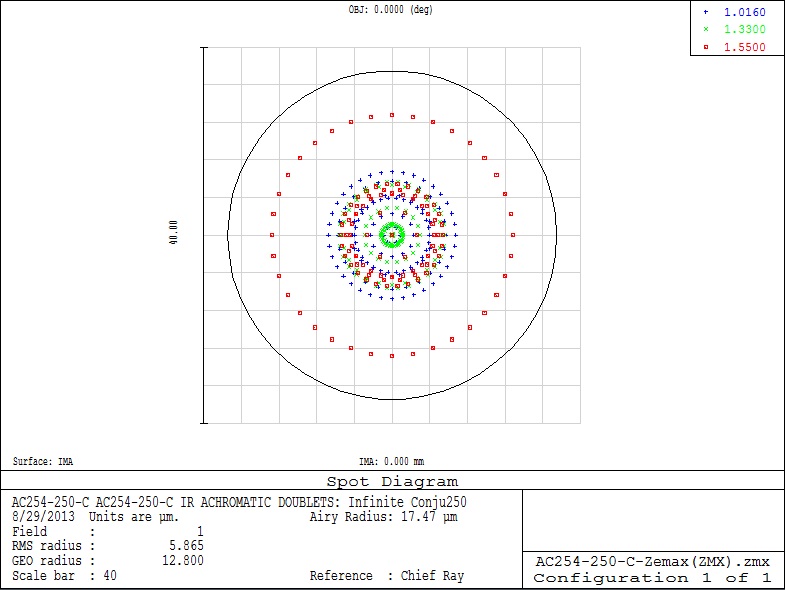
A ray trace for spot size at the image plane of the AC254-200-B is shown below in Figure 3. In this near IR achromatic doublet, the design wavelengths (706.5 nm, 855 nm and 1015 nm) have each been traced through the lens and are represented by different colors. The circle surrounding the distribution of ray intercepts represents the diameter of the Airy disk. If the spot is within the Airy disk, the lens is typically considered to be diffraction limited. Since the spot size is drawn using geometric ray tracing, spots much smaller than the Airy disk are not achievable due to diffraction.
Click to Enlarge
Figure 2
Click to Enlarge
Figure 3
Understanding Modulation Transfer Function, MTF
MTF image quality is an important characteristic of lenses. A common way to measure this is by using contrast. A plot of the modulation transfer function is used as both a theoretical and experimental description of image quality. The MTF of a lens describes its ability to transfer contrast from an object to an image at various resolution levels. Typically, a resolution target made up of black and white lines at various spacings is imaged and contrast can be measured. Contrast at 100% would consist of perfectly black and white lines. As the contrast diminishes, the distinction between lines begins to blur. A plot of MTF shows the percentage of contrast as the spacing between these lines decreases. The spacing between the lines at the object is usually represented as spatial frequency given in cycles/mm.
MTF curves calculated in Zemax® typically present a weighted average with contributions from multiple wavelengths and are known as polychromatic MTF curves. Since shorter and longer wavelengths will have different resolution limits, and hence different individual MTF curves, quantitatively different polychromatic MTF curves may be produced depending on the wavelengths included in the curve's calculation.

Click to Enlarge
Figure 4
The chart shows the theoretical MTF for our Ø25.4 mm, f=200 mm near IR achromatic doublet. The contrast is around 83% at a spatial frequency of about 20 cycles/mm. This represents 83% contrast at 0.05 mm spacings between lines. Theoretical MTF shows how well a design can perform if the optic was built exactly to the design dimensions. In reality, most optics fall short of the theoretical due to manufacturing tolerances.
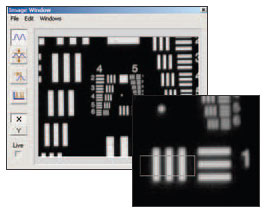
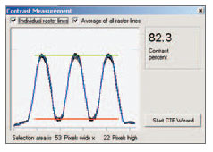
The screen captures to the right and left are actual measurements taken using a USAF 1951 resolution chart as the object.
For the target selected, the contrast measured 82.3%.
Achromatic Doublet Lenses have far superior optical performance to Singlet Lenses. In addition, they offer better broadband and off-axis performance than Aspheric Lenses. Whether your application has demanding imaging requirements or laser beam manipulation needs, these doublets should be considered.
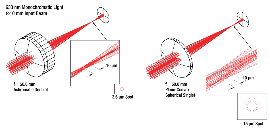
Achieve a Tighter Focus
The figures below show a comparison of a plano-convex singlet focusing a 633 nm laser beam and an achromatic doublet focusing the same laser beam. The spot (circle of least confusion) from the doublet is 4.2 times smaller than the singlet spot size.
Superior Off Axis Performance
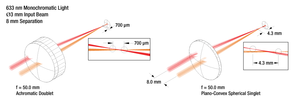
Achromatic doublet lenses have a much reduced sensitivity to centration on the beam axis when compared to spherical singlets and aspheric lenses.
The figures below show two 50.0 mm focal length lenses, one plano-convex and the other an achromatic doublet. Both are Ø25.4 mm lenses with a Ø3 mm beam through the optical axis and one offset by 8.0 mm. Lateral and transverse aberrations are greatly reduced by the achromatic doublet.
Nearly Constant Focal Length Across a Wide Range of Wavelengths
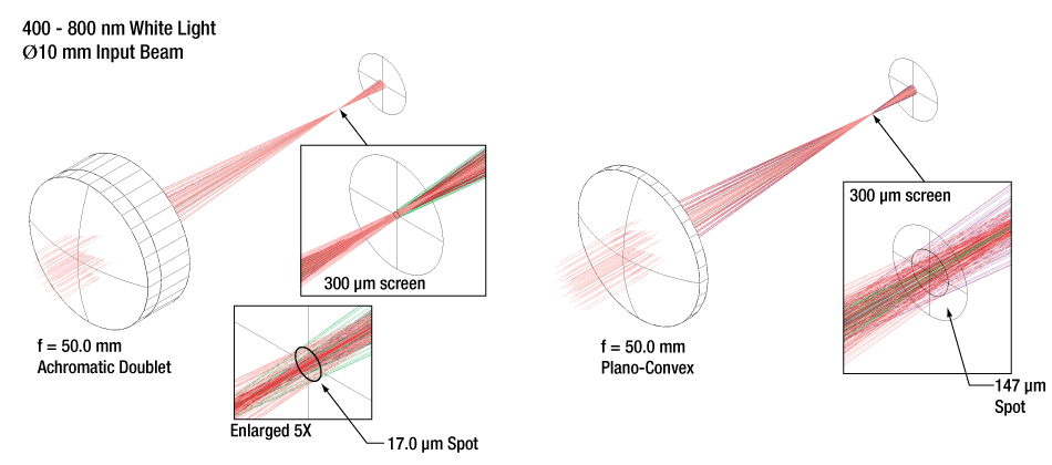
When using a white light source with a singlet lens, the focal point and circle of least confusion are blurred by chromatic aberration. Chromatic aberration is due to the variation of refractive index with respect to wavelength. In an achromatic doublet this effect is somewhat compensated for by using glasses of two different refractive indexes to cancel these aberrations.
The figures below show the effect on focal length for a number of different wavelengths of light through an achromatic doublet and a plano-convex singlet. The figures also shows how the circle of least confusion for white light is reduced by using an achromatic doublet.
| Damage Threshold Specifications | |
|---|---|
| Coating Designation (Item # Suffix) |
Damage Threshold |
| -B (Pulsed) | 5.0 J/cm2 (810 nm, 10 ns, 10 Hz, Ø0.155 mm) |
| -B (CW)a | 1000 W/cm (1070 nm, Ø0.971 mm) |
Damage Threshold Data for Thorlabs' B-Coated Achromatic Doublets
The specifications to the right are measured data for Thorlabs' B-coated achromatic doublets. The damage threshold of cemented achromatic doublets is limited by the cement. For applications that require higher damage thresholds, please consider our air-spaced doublets. These specifications are valid for all AB-coated achromatic doublets, regardless of the size or focal length of the lens.
Laser Induced Damage Threshold Tutorial
The following is a general overview of how laser induced damage thresholds are measured and how the values may be utilized in determining the appropriateness of an optic for a given application. When choosing optics, it is important to understand the Laser Induced Damage Threshold (LIDT) of the optics being used. The LIDT for an optic greatly depends on the type of laser you are using. Continuous wave (CW) lasers typically cause damage from thermal effects (absorption either in the coating or in the substrate). Pulsed lasers, on the other hand, often strip electrons from the lattice structure of an optic before causing thermal damage. Note that the guideline presented here assumes room temperature operation and optics in new condition (i.e., within scratch-dig spec, surface free of contamination, etc.). Because dust or other particles on the surface of an optic can cause damage at lower thresholds, we recommend keeping surfaces clean and free of debris. For more information on cleaning optics, please see our Optics Cleaning tutorial.
Testing Method
Thorlabs' LIDT testing is done in compliance with ISO/DIS 11254 and ISO 21254 specifications.
First, a low-power/energy beam is directed to the optic under test. The optic is exposed in 10 locations to this laser beam for 30 seconds (CW) or for a number of pulses (pulse repetition frequency specified). After exposure, the optic is examined by a microscope (~100X magnification) for any visible damage. The number of locations that are damaged at a particular power/energy level is recorded. Next, the power/energy is either increased or decreased and the optic is exposed at 10 new locations. This process is repeated until damage is observed. The damage threshold is then assigned to be the highest power/energy that the optic can withstand without causing damage. A histogram such as that below represents the testing of one BB1-E02 mirror.
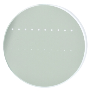
The photograph above is a protected aluminum-coated mirror after LIDT testing. In this particular test, it handled 0.43 J/cm2 (1064 nm, 10 ns pulse, 10 Hz, Ø1.000 mm) before damage.
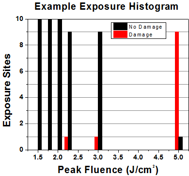
| Example Test Data | |||
|---|---|---|---|
| Fluence | # of Tested Locations | Locations with Damage | Locations Without Damage |
| 1.50 J/cm2 | 10 | 0 | 10 |
| 1.75 J/cm2 | 10 | 0 | 10 |
| 2.00 J/cm2 | 10 | 0 | 10 |
| 2.25 J/cm2 | 10 | 1 | 9 |
| 3.00 J/cm2 | 10 | 1 | 9 |
| 5.00 J/cm2 | 10 | 9 | 1 |
According to the test, the damage threshold of the mirror was 2.00 J/cm2 (532 nm, 10 ns pulse, 10 Hz, Ø0.803 mm). Please keep in mind that these tests are performed on clean optics, as dirt and contamination can significantly lower the damage threshold of a component. While the test results are only representative of one coating run, Thorlabs specifies damage threshold values that account for coating variances.
Continuous Wave and Long-Pulse Lasers
When an optic is damaged by a continuous wave (CW) laser, it is usually due to the melting of the surface as a result of absorbing the laser's energy or damage to the optical coating (antireflection) [1]. Pulsed lasers with pulse lengths longer than 1 µs can be treated as CW lasers for LIDT discussions.
When pulse lengths are between 1 ns and 1 µs, laser-induced damage can occur either because of absorption or a dielectric breakdown (therefore, a user must check both CW and pulsed LIDT). Absorption is either due to an intrinsic property of the optic or due to surface irregularities; thus LIDT values are only valid for optics meeting or exceeding the surface quality specifications given by a manufacturer. While many optics can handle high power CW lasers, cemented (e.g., achromatic doublets) or highly absorptive (e.g., ND filters) optics tend to have lower CW damage thresholds. These lower thresholds are due to absorption or scattering in the cement or metal coating.
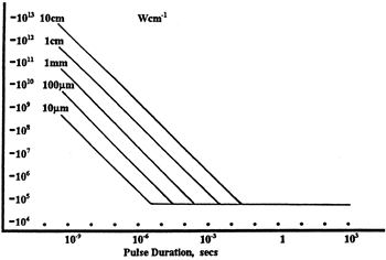
LIDT in linear power density vs. pulse length and spot size. For long pulses to CW, linear power density becomes a constant with spot size. This graph was obtained from [1].
Pulsed lasers with high pulse repetition frequencies (PRF) may behave similarly to CW beams. Unfortunately, this is highly dependent on factors such as absorption and thermal diffusivity, so there is no reliable method for determining when a high PRF laser will damage an optic due to thermal effects. For beams with a high PRF both the average and peak powers must be compared to the equivalent CW power. Additionally, for highly transparent materials, there is little to no drop in the LIDT with increasing PRF.
In order to use the specified CW damage threshold of an optic, it is necessary to know the following:
- Wavelength of your laser
- Beam diameter of your beam (1/e2)
- Approximate intensity profile of your beam (e.g., Gaussian)
- Linear power density of your beam (total power divided by 1/e2 beam diameter)
Thorlabs expresses LIDT for CW lasers as a linear power density measured in W/cm. In this regime, the LIDT given as a linear power density can be applied to any beam diameter; one does not need to compute an adjusted LIDT to adjust for changes in spot size, as demonstrated by the graph to the right. Average linear power density can be calculated using the equation below.

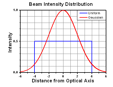
The calculation above assumes a uniform beam intensity profile. You must now consider hotspots in the beam or other non-uniform intensity profiles and roughly calculate a maximum power density. For reference, a Gaussian beam typically has a maximum power density that is twice that of the uniform beam (see lower right).
Now compare the maximum power density to that which is specified as the LIDT for the optic. If the optic was tested at a wavelength other than your operating wavelength, the damage threshold must be scaled appropriately. A good rule of thumb is that the damage threshold has a linear relationship with wavelength such that as you move to shorter wavelengths, the damage threshold decreases (i.e., a LIDT of 10 W/cm at 1310 nm scales to 5 W/cm at 655 nm):

While this rule of thumb provides a general trend, it is not a quantitative analysis of LIDT vs wavelength. In CW applications, for instance, damage scales more strongly with absorption in the coating and substrate, which does not necessarily scale well with wavelength. While the above procedure provides a good rule of thumb for LIDT values, please contact Tech Support if your wavelength is different from the specified LIDT wavelength. If your power density is less than the adjusted LIDT of the optic, then the optic should work for your application.
Please note that we have a buffer built in between the specified damage thresholds online and the tests which we have done, which accommodates variation between batches. Upon request, we can provide individual test information and a testing certificate. The damage analysis will be carried out on a similar optic (customer's optic will not be damaged). Testing may result in additional costs or lead times. Contact Tech Support for more information.
Pulsed Lasers
As previously stated, pulsed lasers typically induce a different type of damage to the optic than CW lasers. Pulsed lasers often do not heat the optic enough to damage it; instead, pulsed lasers produce strong electric fields capable of inducing dielectric breakdown in the material. Unfortunately, it can be very difficult to compare the LIDT specification of an optic to your laser. There are multiple regimes in which a pulsed laser can damage an optic and this is based on the laser's pulse length. The highlighted columns in the table below outline the relevant pulse lengths for our specified LIDT values.
Pulses shorter than 10-9 s cannot be compared to our specified LIDT values with much reliability. In this ultra-short-pulse regime various mechanics, such as multiphoton-avalanche ionization, take over as the predominate damage mechanism [2]. In contrast, pulses between 10-7 s and 10-4 s may cause damage to an optic either because of dielectric breakdown or thermal effects. This means that both CW and pulsed damage thresholds must be compared to the laser beam to determine whether the optic is suitable for your application.
| Pulse Duration | t < 10-9 s | 10-9 < t < 10-7 s | 10-7 < t < 10-4 s | t > 10-4 s |
|---|---|---|---|---|
| Damage Mechanism | Avalanche Ionization | Dielectric Breakdown | Dielectric Breakdown or Thermal | Thermal |
| Relevant Damage Specification | No Comparison (See Above) | Pulsed | Pulsed and CW | CW |
When comparing an LIDT specified for a pulsed laser to your laser, it is essential to know the following:
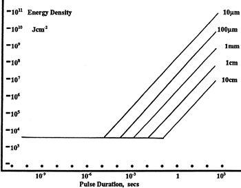
LIDT in energy density vs. pulse length and spot size. For short pulses, energy density becomes a constant with spot size. This graph was obtained from [1].
- Wavelength of your laser
- Energy density of your beam (total energy divided by 1/e2 area)
- Pulse length of your laser
- Pulse repetition frequency (prf) of your laser
- Beam diameter of your laser (1/e2 )
- Approximate intensity profile of your beam (e.g., Gaussian)
The energy density of your beam should be calculated in terms of J/cm2. The graph to the right shows why expressing the LIDT as an energy density provides the best metric for short pulse sources. In this regime, the LIDT given as an energy density can be applied to any beam diameter; one does not need to compute an adjusted LIDT to adjust for changes in spot size. This calculation assumes a uniform beam intensity profile. You must now adjust this energy density to account for hotspots or other nonuniform intensity profiles and roughly calculate a maximum energy density. For reference a Gaussian beam typically has a maximum energy density that is twice that of the 1/e2 beam.
Now compare the maximum energy density to that which is specified as the LIDT for the optic. If the optic was tested at a wavelength other than your operating wavelength, the damage threshold must be scaled appropriately [3]. A good rule of thumb is that the damage threshold has an inverse square root relationship with wavelength such that as you move to shorter wavelengths, the damage threshold decreases (i.e., a LIDT of 1 J/cm2 at 1064 nm scales to 0.7 J/cm2 at 532 nm):

You now have a wavelength-adjusted energy density, which you will use in the following step.
Beam diameter is also important to know when comparing damage thresholds. While the LIDT, when expressed in units of J/cm², scales independently of spot size; large beam sizes are more likely to illuminate a larger number of defects which can lead to greater variances in the LIDT [4]. For data presented here, a <1 mm beam size was used to measure the LIDT. For beams sizes greater than 5 mm, the LIDT (J/cm2) will not scale independently of beam diameter due to the larger size beam exposing more defects.
The pulse length must now be compensated for. The longer the pulse duration, the more energy the optic can handle. For pulse widths between 1 - 100 ns, an approximation is as follows:

Use this formula to calculate the Adjusted LIDT for an optic based on your pulse length. If your maximum energy density is less than this adjusted LIDT maximum energy density, then the optic should be suitable for your application. Keep in mind that this calculation is only used for pulses between 10-9 s and 10-7 s. For pulses between 10-7 s and 10-4 s, the CW LIDT must also be checked before deeming the optic appropriate for your application.
Please note that we have a buffer built in between the specified damage thresholds online and the tests which we have done, which accommodates variation between batches. Upon request, we can provide individual test information and a testing certificate. Contact Tech Support for more information.
[1] R. M. Wood, Optics and Laser Tech. 29, 517 (1998).
[2] Roger M. Wood, Laser-Induced Damage of Optical Materials (Institute of Physics Publishing, Philadelphia, PA, 2003).
[3] C. W. Carr et al., Phys. Rev. Lett. 91, 127402 (2003).
[4] N. Bloembergen, Appl. Opt. 12, 661 (1973).
In order to illustrate the process of determining whether a given laser system will damage an optic, a number of example calculations of laser induced damage threshold are given below. For assistance with performing similar calculations, we provide a spreadsheet calculator that can be downloaded by clicking the button to the right. To use the calculator, enter the specified LIDT value of the optic under consideration and the relevant parameters of your laser system in the green boxes. The spreadsheet will then calculate a linear power density for CW and pulsed systems, as well as an energy density value for pulsed systems. These values are used to calculate adjusted, scaled LIDT values for the optics based on accepted scaling laws. This calculator assumes a Gaussian beam profile, so a correction factor must be introduced for other beam shapes (uniform, etc.). The LIDT scaling laws are determined from empirical relationships; their accuracy is not guaranteed. Remember that absorption by optics or coatings can significantly reduce LIDT in some spectral regions. These LIDT values are not valid for ultrashort pulses less than one nanosecond in duration.

A Gaussian beam profile has about twice the maximum intensity of a uniform beam profile.
CW Laser Example
Suppose that a CW laser system at 1319 nm produces a 0.5 W Gaussian beam that has a 1/e2 diameter of 10 mm. A naive calculation of the average linear power density of this beam would yield a value of 0.5 W/cm, given by the total power divided by the beam diameter:

However, the maximum power density of a Gaussian beam is about twice the maximum power density of a uniform beam, as shown in the graph to the right. Therefore, a more accurate determination of the maximum linear power density of the system is 1 W/cm.
An AC127-030-C achromatic doublet lens has a specified CW LIDT of 350 W/cm, as tested at 1550 nm. CW damage threshold values typically scale directly with the wavelength of the laser source, so this yields an adjusted LIDT value:

The adjusted LIDT value of 350 W/cm x (1319 nm / 1550 nm) = 298 W/cm is significantly higher than the calculated maximum linear power density of the laser system, so it would be safe to use this doublet lens for this application.
Pulsed Nanosecond Laser Example: Scaling for Different Pulse Durations
Suppose that a pulsed Nd:YAG laser system is frequency tripled to produce a 10 Hz output, consisting of 2 ns output pulses at 355 nm, each with 1 J of energy, in a Gaussian beam with a 1.9 cm beam diameter (1/e2). The average energy density of each pulse is found by dividing the pulse energy by the beam area:

As described above, the maximum energy density of a Gaussian beam is about twice the average energy density. So, the maximum energy density of this beam is ~0.7 J/cm2.
The energy density of the beam can be compared to the LIDT values of 1 J/cm2 and 3.5 J/cm2 for a BB1-E01 broadband dielectric mirror and an NB1-K08 Nd:YAG laser line mirror, respectively. Both of these LIDT values, while measured at 355 nm, were determined with a 10 ns pulsed laser at 10 Hz. Therefore, an adjustment must be applied for the shorter pulse duration of the system under consideration. As described on the previous tab, LIDT values in the nanosecond pulse regime scale with the square root of the laser pulse duration:

This adjustment factor results in LIDT values of 0.45 J/cm2 for the BB1-E01 broadband mirror and 1.6 J/cm2 for the Nd:YAG laser line mirror, which are to be compared with the 0.7 J/cm2 maximum energy density of the beam. While the broadband mirror would likely be damaged by the laser, the more specialized laser line mirror is appropriate for use with this system.
Pulsed Nanosecond Laser Example: Scaling for Different Wavelengths
Suppose that a pulsed laser system emits 10 ns pulses at 2.5 Hz, each with 100 mJ of energy at 1064 nm in a 16 mm diameter beam (1/e2) that must be attenuated with a neutral density filter. For a Gaussian output, these specifications result in a maximum energy density of 0.1 J/cm2. The damage threshold of an NDUV10A Ø25 mm, OD 1.0, reflective neutral density filter is 0.05 J/cm2 for 10 ns pulses at 355 nm, while the damage threshold of the similar NE10A absorptive filter is 10 J/cm2 for 10 ns pulses at 532 nm. As described on the previous tab, the LIDT value of an optic scales with the square root of the wavelength in the nanosecond pulse regime:

This scaling gives adjusted LIDT values of 0.08 J/cm2 for the reflective filter and 14 J/cm2 for the absorptive filter. In this case, the absorptive filter is the best choice in order to avoid optical damage.
Pulsed Microsecond Laser Example
Consider a laser system that produces 1 µs pulses, each containing 150 µJ of energy at a repetition rate of 50 kHz, resulting in a relatively high duty cycle of 5%. This system falls somewhere between the regimes of CW and pulsed laser induced damage, and could potentially damage an optic by mechanisms associated with either regime. As a result, both CW and pulsed LIDT values must be compared to the properties of the laser system to ensure safe operation.
If this relatively long-pulse laser emits a Gaussian 12.7 mm diameter beam (1/e2) at 980 nm, then the resulting output has a linear power density of 5.9 W/cm and an energy density of 1.2 x 10⁻⁴ J/cm2 per pulse. This can be compared to the LIDT values for a WPQ10E-980 polymer zero-order quarter-wave plate, which are 5 W/cm for CW radiation at 810 nm and 5 J/cm2 for a 10 ns pulse at 810 nm. As before, the CW LIDT of the optic scales linearly with the laser wavelength, resulting in an adjusted CW value of 6 W/cm at 980 nm. On the other hand, the pulsed LIDT scales with the square root of the laser wavelength and the square root of the pulse duration, resulting in an adjusted value of 55 J/cm2 for a 1 µs pulse at 980 nm. The pulsed LIDT of the optic is significantly greater than the energy density of the laser pulse, so individual pulses will not damage the wave plate. However, the large average linear power density of the laser system may cause thermal damage to the optic, much like a high-power CW beam.
| Posted Comments: | |
Kilian Muller
(posted 2024-04-25 15:01:08.15) Hi,
I am using your AC508-080-B lens as the final lens in a collimator. The light should be linearly polarised. However, using your PAX1000 polarimeter I find that there is a finite ellipticity of the beam. Curiously, this ellipticity depends on:
- the orientation of the lens (rotating the lens while leaving everything else constant the ellipticity oscillates between -0.7° and +0.7° or so.
- the distance from the optical axis, with the ellipticity increasing to about 2° towards the edges of the beam.
I am in the process of finding the cause of this behaviour and wonder: do cemented doublet lenses maybe tend to be birefringent? I could imagine mechanical stress being introduced due to gluing the two lenses together.
Cheers! cdolbashian
(posted 2024-05-06 09:35:51.0) Thank you for contacting Thorlabs. The cement would induce stress between the two pieces of the doublets, especially on the edge, given the consideration that one of the lenses has much thinner edge compared with the other one. Unfortunately, we currently don't have any data about the change of the beam's polarization when passes though the doublets. user
(posted 2022-11-24 08:45:14.577) The text and the graphics in the Performance-Tab do not properly match. The text adresses the spot diagram of the A254-200-B and its corresponding wavelengths. However, the graph of the spot diagram depicts the performance of the lens A254-250-C.
This is relevant for me, since I want to reproduce the results that you show without having Zemax.
It would also be helpful for me to know how you exactly setup up the simulation in order to get the results. But this topic we might possibly discuss directly. cdolbashian
(posted 2022-12-02 04:23:58.0) Thank you for pointing out this error. The incorrect image will be replaced shortly. Zemax documents can be downloaded by clicking on the red "Docs" icon in front of the part number on the product page in the overview tab. We will reach out to you directly about providing Zemax documents. Srinivas Varma Pericherla
(posted 2021-02-25 15:17:12.94) Hi,
I want to ask if you guys have
AC508-150-B with flattened focal shift at 970 nm.This lens are for 4f grating compressor system. I have also sent a request for AC508-180-AB too.
Thanks YLohia
(posted 2021-03-05 10:00:05.0) Hello, custom items can be requested by using the "Request Quote" above or by emailing your local Thorlabs team (in your case, techsupport@thorlabs.com). We will discuss the possibility of offering this directly. Tomoki Hori
(posted 2020-01-24 19:24:02.833) 3DCADデータと実物で刻印の向きが逆になっております。確認及び修正をお願いいたします。 YLohia
(posted 2020-01-24 09:48:15.0) Thank you for contacting Thorlabs. Our Tech Support team in Japan will reach out to you directly. hxiahui
(posted 2014-03-06 14:12:52.097) My Zemax also shows cann't open 'COATINGTHRO.DAT',when it is running the .zmx file. Can you send me a copy of this file by email? jlow
(posted 2014-03-06 03:54:17.0) Response from Jeremy at Thorlabs: We recommend using the .zar files which are a pack and go Zemax zip file which contain both the coating and the lens data. A simple solution would be to remove the coating from the lens if you cannot use the .zar file format. louischianga
(posted 2014-01-09 10:19:29.577) Zemax show (coatings 'COATINGTHRO.DAT' can't open).Please tell me where can be found the 'COATINGTHRO.DAT' . Thank you ! tcohen
(posted 2014-01-09 03:49:47.0) Response from Tim at Thorlabs: Thanks for contacting us. If you can load the .zar file with your edition instead, it automatically provides all referenced files. If you would like to use the .zmx file, you can find the ‘COATINGTHOR.DAT’ file in the Coatings folder you chose as the Zemax install location. The default location should be: C:\Documents and Settings\[USER]\My Documents\Zemax\Coatings. I’ve contacted your email in case you need a copy of this file. dreamangelfly
(posted 2013-04-13 16:59:32.78) Excuse me, I've one question. I have two lens (ACN254-050-B and AC254-150-B), and I want to use them to be one beam expander by 532nm laser. But the spectra of them are only from 650 to 1050nm. Can you send me the spectra of these two lens from visible light or 300 to 700nm, please. Thanks a lot. tcohen
(posted 2013-04-18 15:27:00.0) Response from Tim at Thorlabs: Thank you for contacting us. Using our coated optics outside of their design wavelength will often cause the reflections to be worse than an uncoated optic. One data set taken on the AC254-150-B showed the transmission to have fallen to 80% by 550nm. Also, if you are looking to use this with multiple wavelengths (300-700nm) outside of the design wavelength we must be aware that the substrates are specifically engineered to provide the best achromatic performance in a target wavelength range. The performance outside this range in terms of chromatic focal length shift will fall off in addition to the increased reflection. We do supply a variety of –A coated visible achromats which may be better suited. I will contact you with our data. tcohen
(posted 2013-02-21 15:01:00.0) Response from Tim at Thorlabs: Thank you for your inquiry! The 80mm version is now available on the website (AC254-080-B-ML) and we shall follow with the 125mm version in a few days. tcohen
(posted 2012-11-08 10:12:00.0) Response from Tim at Thorlabs: The focal shift in this case will be >7 times smaller for the achromat. I will send you data on both for your review. madhavi.krishnan
(posted 2012-11-08 07:30:01.063) We are developing an imaging system and would like to focus two different laser on a camera chip. At the moment we are using a 750 mm bi-convex lens (LB1247-B). What is focal plane shift expected from this lens using 671 nm and 1064 nm laser lines? We are now buying the AC508-750-B to improve the discrepancy but from the website the data for focal plane shifts are missing both for the lens we are using now and for the achromatic we are about to buy. Could you please send us datasheets for both (if available)? jjurado
(posted 2011-05-16 12:40:00.0) Response from Javier at Thorlabs to cumn333: Thank you very much for your feedback. I will share your comments with our optics department and will also keep you updated if we decide to add this product to our offerings. cumn333
(posted 2011-05-15 12:27:28.0) AC254-125-B should be provided. 125 mm focal length achromatic lens should be available from Thorlabs. Now I have to order them from Edmund optics. Thorlabs should have this product. jjurado
(posted 2011-03-03 11:35:00.0) Reply from Javier at Thorlabs to Matt Kirchner: Thank you for your feedback. We will discuss the possibility of adding achromats in these sizes and focal lengths to our catalog. I will keep you updated with the status of this project. mkirchne
(posted 2011-03-02 19:51:03.0) I would really like it if you made a 3" (76.2 mm) or 4" (101.6 mm) diameter NIR achromatic lens at long focal lengths (500 mm, 750 mm, 1000 mm). The only large achromats I have found are designed for the visible (edmund and newport).
-Matt Kirchner jjurado
(posted 2011-02-04 13:38:00.0) Response from Javier at Thorlabs to smuehlen: Thank you for contacting us! The bonding used for our achromatic doublets is not UHV compatible. Also, we would not recommend exceeding 85 degrees Celsius, as permanent damage is very likely to occur above this temperature. Finally, we can certainly provide the two lenses separately. I will contact you directly to process a quotation. smuehlen
(posted 2011-02-03 14:50:02.0) Is the bonding you use UHV compatible? What is the maximum temperature that the doublet can be exposed to without damaging it permanently (not the operating temperature)? Is there any possibility to get the two lenses separately? Buki at Thorlabs
(posted 2011-01-27 02:49:50.0) The limiting factor of the damage threshold for these achromatic doublet is the cement that holds the doublets together, not the coating. A conservative guideline is 100W/cm^2 for 200 hours. We will soon offer high powered air spaced doublets. Please contact TechSupport@thorlabs.com for more information. user
(posted 2011-01-26 14:09:39.0) Damage threshold question, adhesive is tougher than coating? Thorlabs
(posted 2010-07-01 09:08:40.0) Response from Javier at Thorlabs to aglinz: the operating temperature for these achromatic doublets is -40 to 85 degrees Celsius. aglinz
(posted 2010-07-01 03:34:24.0) Please tell me the temperature range for which this cemented achromatic doublet is specified.
A short answer would be highly appreciated!
Thanks for your time and efforts.
Kind regards
Andreas Glinz |

| Item # | Diameter (mm) |
f a (mm) |
fba (mm) |
Graphsb | R1a (mm) |
R2a (mm) |
R3a (mm) |
tc1 (mm) |
tc2 (mm) |
tec (mm) |
Materialsd | Compatible Fixed Lens Mounts |
Reference Drawing |
|---|---|---|---|---|---|---|---|---|---|---|---|---|---|
| AC050-008-B | 5.0 | 7.5 | 4.8 | 4.6 | -3.9 | -36.0 | 2.8 | 1.8 | 3.8 | N-BAF10/N-SF6HT | MLH5(/M) See Footnote e |
||
| AC050-010-B | 5.0 | 10.0 | 8.0 | 6.6 | -5.3 | -24.9 | 2.2 | 1.6 | 3.2 | N-LAK22/N-SF6HT | MLH5(/M) LMR5(/M) See Footnote e |
||
| AC050-015-B | 5.0 | 15.0 | 13.0 | 10.3 | -7.6 | -32.1 | 2.3 | 1.7 | 3.6 | N-LAK22/N-SF6HT | MLH5(/M) See Footnote e |

| Item # | Diameter (mm) |
f a (mm) |
fba (mm) |
Graphsb | R1a (mm) |
R2a (mm) |
R3a (mm) |
tc1 (mm) |
tc2 (mm) |
tec (mm) |
Materialsd | Compatible Fixed Lens Mounts |
Reference Drawing |
|---|---|---|---|---|---|---|---|---|---|---|---|---|---|
| AC064-013-B | 6.35 | 12.7 | 10.7 | 8.6 | -6.7 | -29.0 | 2.5 | 1.4 | 3.1 | N-LAK22/N-SF6HT | MLH7(/M) LMR7(/M) See Footnote e |
||
| AC064-015-B | 6.35 | 15.0 | 13.1 | 10.3 | -7.8 | -32.9 | 2.4 | 1.5 | 3.2 | N-LAK22/N-SF6HT |

| Item # | Diameter (mm) |
f a (mm) |
fba (mm) |
Graphsb | R1a (mm) |
R2a (mm) |
R3a (mm) |
tc1 (mm) |
tc2 (mm) |
tec (mm) |
Materialsd | Compatible Fixed Lens Mounts |
Reference Drawing |
|---|---|---|---|---|---|---|---|---|---|---|---|---|---|
| AC080-010-B | 8.0 | 10.0 | 7.0 | 7.6 | -4.6 | -30.6 | 4.5 | 1.3 | 4.4 | N-LAK10/N-SF6HT | MLH8(/M) See Footnote e |
||
| AC080-016-B | 8.0 | 16.0 | 14.0 | 11.0 | -8.6 | -35.8 | 2.5 | 1.5 | 3.0 | N-LAK22/N-SF6HT | MLH8(/M) LMR8(/M) See Footnote e |
||
| AC080-020-B | 8.0 | 20.0 | 18.2 | 13.5 | -10.6 | -47.8 | 2.3 | 1.3 | 2.8 | N-LAK22/N-SF6HT | |||
| AC080-030-B | 8.0 | 30.0 | 27.7 | 18.5 | -16.2 | -106.0 | 2.5 | 1.5 | 3.5 | N-LAK22/N-SF6 |

| Item # | Diameter (mm) |
f a (mm) |
fba (mm) |
Graphsb | R1a (mm) |
R2a (mm) |
R3a (mm) |
tc1 (mm) |
tc2 (mm) |
tec (mm) |
Materialsd | Compatible Fixed Lens Mounts |
Reference Drawing |
|---|---|---|---|---|---|---|---|---|---|---|---|---|---|
| ACN127-020-B | 12.7 | -20.0 | -22.5 | -12.3 | 14.0 | 152.8 | 1.5 | 3.0 | 6.4 | N-BAF10/N-SF6HT | See Footnote e | ||
| ACN127-025-B | 12.7 | -25.0 | -27.7 | -13.6 | 17.1 | -859.0 | 1.5 | 2.8 | 5.9 | N-BAF10/N-SF6HT | |||
| ACN127-030-B | 12.7 | -30.0 | -32.0 | -19.3 | 18.4 | 106.4 | 1.5 | 2.5 | 5.3 | N-LAK22/N-SF6HT | MLH05(/M) | ||
| ACN127-050-B | 12.7 | -50.0 | -52.5 | -24.4 | 30.4 | -291.1 | 1.5 | 2.0 | 4.3 | N-BAF10/N-SF6HT | MLH05(/M) LMR05(/M) LMR05V(/M) LMR05S(/M) |
||
| AC127-019-B | 12.7 | 19.0 | 15.5 | 12.2 | -10.6 | -77.4 | 4.5 | 1.5 | 3.9 | N-BAF10/N-SF6HT | MLH05(/M) LMR05(/M) LMR05V(/M) LMR05S(/M) SMR05(/M) |
||
| AC127-025-B | 12.7 | 25.0 | 21.1 | 16.2 | -13.3 | -68.5 | 5.0 | 2.0 | 5.4 | N-LAK22/N-SF6HT | See Footnote e | ||
| AC127-030-B | 12.7 | 30.0 | 27.3 | 19.8 | -16.2 | -79.1 | 3.5 | 1.5 | 3.7 | N-LAK22/N-SF6HT | MLH05(/M) LMR05(/M) LMR05V(/M) LMR05S(/M) SMR05(/M) |
||
| AC127-050-B | 12.7 | 50.0 | 46.2 | 24.2 | -26.8 | 250.0 | 3.5 | 1.5 | 4.2 | N-BAF10/N-SF6HT | MLH05(/M) LMR05(/M) LMR05V(/M) LMR05S(/M) |
||
| AC127-075-B | 12.7 | 75.0 | 72.0 | 36.2 | -40.4 | 398.1 | 2.5 | 1.5 | 3.5 | N-BAF10/N-SF6HT | MLH05(/M) LMR05(/M) LMR05V(/M) LMR05S(/M) SMR05(/M) |

| Item # | Diameter (mm) |
f a (mm) |
fba (mm) |
Graphsb | R1a (mm) |
R2a (mm) |
R3a (mm) |
tc1 (mm) |
tc2 (mm) |
tec (mm) |
Materialsd | Compatible Fixed Lens Mounts |
Reference Drawing |
|---|---|---|---|---|---|---|---|---|---|---|---|---|---|
| ACN254-040-B | 25.4 | -40.0 | -43.4 | -24.43 | 27.86 | 332.30 | 2.0 | 4.0 | 9.8 | N-BAF10/N-SF6HT | See Footnote e | ||
| ACN254-050-B | 25.4 | -50.0 | -53.8 | -27.05 | 33.91 | -1330.50 | 2.0 | 4.0 | 9.1 | N-BAF10/N-SF6HT | |||
| ACN254-075-B | 25.4 | -75.0 | -78.9 | -37.14 | 46.39 | -494.3 | 2.0 | 3.8 | 7.9 | N-BAF10/N-SF6HT | |||
| ACN254-100-B | 25.4 | -100.1 | -103.9 | -48.8 | 59.0 | -580.8 | 2.0 | 3.4 | 6.9 | N-BAF10/N-SF6HT | LMR1(/M) LMR1V(/M) LMR1S(/M) |
||
| AC254-030-B | 25.4 | 30.0 | 23.0 | 21.09 | -16.18 | -79.08 | 12.0 | 1.5 | 8.2 | N-BAF10/N-SF6HT | See Footnote e | ||
| AC254-035-B | 25.4 | 35.0 | 28.4 | 23.99 | -18.62 | -97.27 | 10.5 | 1.5 | 7.5 | N-BAF10/N-SF6HT | |||
| AC254-040-B | 25.4 | 40.0 | 32.8 | 26.12 | -21.28 | -137.09 | 10 | 2.5 | 8.6 | N-BAF10/N-SF6HT | |||
| AC254-045-B | 25.4 | 45.0 | 39.6 | 29.38 | -25.05 | -127.06 | 7.8 | 1.6 | 5.9 | N-LAK22/N-SF6HT | LMR1(/M) LMR1V(/M) LMR1S(/M) SMR1(/M) |
||
| AC254-050-B | 25.4 | 50.0 | 45.0 | 33.55 | -27.05 | -125.60 | 7.5 | 1.8 | 6.2 | N-LAK22/N-SF6HT | LMR1(/M) LMR1V(/M) LMR1S(/M) |
||
| AC254-060-B | 25.4 | 60.0 | 55.8 | 39.48 | -33.00 | -165.20 | 6.0 | 1.7 | 5.1 | N-LAK22/N-SF6HT | LMR1(/M) LMR1V(/M) LMR1S(/M) SMR1(/M) |
||
| AC254-075-B | 25.4 | 75.0 | 69.9 | 36.90 | -42.17 | 417.8 | 5.0 | 1.6 | 4.5 | N-BAF10/N-SF6HT | |||
| AC254-080-B | 25.4 | 80.3 | 73.5 | 38.7 | -43.2 | 374.0 | 6.6 | 2.0 | 6.4 | N-BAF10/N-SF6HT | LMR1(/M) LMR1V(/M) LMR1S(/M) |
||
| AC254-100-B | 25.4 | 100.0 | 97.1 | 66.68 | -53.70 | -259.41 | 4.0 | 1.5 | 4.0 | N-LAK22/N-SF6HT | LMR1(/M) LMR1V(/M) LMR1S(/M) SMR1(/M) |
||
| AC254-125-B | 25.4 | 125.0 | 115.4 | 44.5 | -55.3 | 930.5 | 6.0 | 6.0 | 10.0 | N-BK7/N-SF8 | See Footnote e | ||
| AC254-150-B | 25.4 | 150.0 | 144.6 | 83.60 | -89.33 | -1330.50 | 4.0 | 3.5 | 6.5 | N-LAK22/N-SF6HT | LMR1(/M) LMR1V(/M) LMR1S(/M) |
||
| AC254-200-B | 25.4 | 200.0 | 194.8 | 106.4 | -96.6 | 2000.0 | 4.0 | 4.0 | 7.3 | N-LAK22/N-SF10 | See Footnote e | ||
| AC254-250-B | 25.4 | 250.0 | 237.5 | 52.00 | -65.31 | 111.51 | 4.0 | 1.5 | 4.7 | SF5/N-SF6HT | LMR1(/M) LMR1V(/M) LMR1S(/M) SMR1(/M) |
||
| AC254-300-B | 25.4 | 300.0 | 290.0 | 62.40 | -77.40 | 134.00 | 4.0 | 2.0 | 5.3 | SF5/N-SF6HT | |||
| AC254-400-B | 25.4 | 400.0 | 391.1 | 83.60 | -106.41 | 181.55 | 3.5 | 1.8 | 4.8 | SF5/N-SF6HT | |||
| AC254-500-B | 25.4 | 500.0 | 480.8 | 60.60 | -62.75 | 87.57 | 4.0 | 2.0 | 5.6 | N-SF10/N-SF6HT |

| Item # | Diameter (mm) |
f a (mm) |
fba (mm) |
Graphsb | R1a (mm) |
R2a (mm) |
R3a (mm) |
tc1 (mm) |
tc2 (mm) |
tec (mm) |
Materialsd | Compatible Fixed Lens Mounts |
Reference Drawing |
|---|---|---|---|---|---|---|---|---|---|---|---|---|---|
| AC300-050-B | 30.0 | 50.0 | 42.9 | 30.8 | -27.9 | -272.9 | 9.5 | 2.0 | 7.2 | N-BAF10/N-SF6HT | See Footnote e | ||
| AC300-080-B | 30.0 | 80.0 | 75.3 | 52.5 | -42.7 | -216.3 | 6.5 | 2.0 | 5.8 | N-LAK22/N-SF6HT | LMR30(/M) | ||
| AC300-100-B | 30.0 | 100.0 | 94.0 | 49.1 | -55.3 | 557.4 | 6.0 | 2.0 | 5.9 | N-BAF10/N-SF6HT |

| Item # | Diameter (mm) |
f a (mm) |
fba (mm) |
Graphsb | R1a (mm) |
R2a (mm) |
R3a (mm) |
tc1 (mm) |
tc2 (mm) |
tec (mm) |
Materialsd | Compatible Fixed Lens Mounts |
Reference Drawing |
|---|---|---|---|---|---|---|---|---|---|---|---|---|---|
| AC508-075-B | 50.8 | 75.0 | 65.7 | 51.8 | -93.1 | -291.1 | 12.0 | 5.0 | 9.2 | N-LAK22/N-SF6HT | LMR2(/M) LMR2V(/M) LMR2S(/M) |
||
| AC508-080-B | 50.8 | 80.0 | 69.5 | 51.8 | -44.6 | -312.6 | 16.0 | 2.0 | 10.3 | N-BAF10/N-SF6HT | See Footnote e | ||
| AC508-100-B | 50.8 | 100.0 | 91.5 | 65.8 | -56.0 | -280.6 | 13.0 | 2.0 | 8.7 | N-LAK22/N-SF6HT | See Footnote f | ||
| AC508-150-B | 50.8 | 150.0 | 145.3 | 112.2 | -95.9 | -325.1 | 8.2 | 5.0 | 9.3 | N-LAK22/N-SF6HT | |||
| ACT508-200-B | 50.8 | 200.0 | 193.2 | 121.0 | -118.7 | -422.2 | 8.2 | 5.0 | 9.8 | N-SK2/N-SF57 | See Footnote e | ||
| ACT508-250-B | 50.8 | 250.0 | 241.8 | 137.7 | -137.7 | -930.4 | 8.1 | 6.0 | 11.4 | N-SK2/N-SF11 | |||
| ACT508-300-B | 50.8 | 300.0 | 291.4 | 158.1 | -171.1 | -1529.9 | 8.0 | 6.0 | 11.8 | N-SK2/N-SF11 | |||
| ACT508-400-B | 50.8 | 400.0 | 389.5 | 189.8 | -152.8 | 2290.9 | 8.0 | 6.0 | 12.5 | N-SK2/N-SF5 | |||
| ACT508-500-B | 50.8 | 500.0 | 491.1 | 233.8 | -192.8 | 2471.1 | 6.0 | 6.0 | 10.8 | N-SK2/N-SF5 | |||
| ACT508-750-B | 50.8 | 750.0 | 742.4 | 386.7 | -269.6 | Plano | 6.0 | 5.0 | 10.2 | N-SK2/N-SF5 | |||
| ACT508-1000-B | 50.8 | 1000.0 | 991.1 | 465.2 | -388.7 | 4726.2 | 6.0 | 6.0 | 11.4 | N-SK2/N-SF5 |
 Products Home




 650 - 1050 nm Unmounted Achromatic Doublets