30 mm Cage Cubes
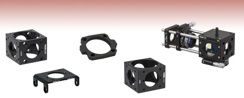
- Build 2D and 3D Cage Systems with Cage Cubes
- Integrates into 30 mm Cage Systems
- Compatible with 30 mm Optics Holders, Platforms, and Accessories
C6WR
C4W-CC
CPG3
C4W
4-40 Tapped Holes for ER Rods
Application Idea

Please Wait
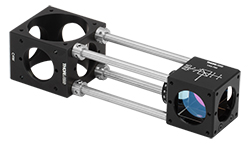
Click to Enlarge ERSCB Cage Rod Adapters are Used to Connect the C4W Cage Cube to a VA5-780 Variable Beamsplitter Cube
Features
- 30 mm Cage System- and SM1 Lens Tube-Compatible Cubes
- Build 2D and 3D Cage and Lens Tube Systems
The 30 mm cage cubes offered here are ideal for building optical setups involving prisms, beamsplitters, and other optics that cause a 90° deviation of the beam path. They are compatible with the accessories sold below, those featured in the table below, as well as our selection of 30 mm Cage Accessories and Cage Components. The Application Ideas tab shows how to use our cage cubes and accessories to construct a beam combiner with a dichroic mirror as well as a variable attenuation beamsplitter with a polarizing beamsplitting cube. Shown to the right, the C4W 30 mm Cage Cube is connected to a VA5-780 Variable Beamsplitter Cube using cage rods and four ERSCB Rod Adapters. The ERSCB Rod Adapters are required when trying to connect any two cage cubes.
Thorlabs offers a wide and growing complement of accessories for 30 mm cage cubes, including optic mounts, platforms, rotating platforms, and cover plates. These tools provide a complete family of versatile building blocks suited for virtually any 30 mm cage cube optomechanical setup.
We also offer smaller 1.5" cage cubes that are ideal for mounting prisms and cube-shaped optics, as well as a dichroic cage cube with a built-in FFM1 mount.
| 30 mm Cage Cubes and Accessories | ||||
|---|---|---|---|---|
 |
 |
 |
 |
 |
| Cage Cubes | Optic Mounts | Platforms | Rotating Platforms | Cover Plates |
| Alternative Size Options |
|---|
| 16 mm Cage Cubes |
| 2" Wide 30 mm Cage Cubes |
| 1.5" Wide 30 mm Cage Cubes |
| 60 mm Cage Cubes |
Combining Two Beams
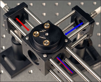
Our cage system can be used to build an easily adjustable beam combiner. This setup is based on the use of an appropriate dichroic mirror for the wavelengths that need to be combined. One beam needs to be in the transmission band of the dichroic mirror, while the other needs to be in the reflection band. For this application the reflection band laser is 405 nm and the transmission band laser is 635 nm. The DMLP567 is an appropriate dichroic mirror for the two selected wavelengths.
The dichroic mirror is mounted in a B5CT1 threaded Ø1" optic mount and attached to a B4C kinematic platform. The kinematic platform allows for positioning of the beam that is within the reflection band of the dichroic mirror. This assembly is placed within a C4W cage cube with ER cage rods attached to two adjacent faces. One set of cage rods holds a collimator for the reflection band's fiber coupled laser, while the other set of cage rods holds a collimator for the transmission band's fiber coupled laser.
A more complex setup can be built to combine more than two beams by using multiple dichroic mirrors together.
Variable Attenuation Beamsplitter
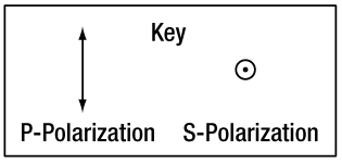
In normal operation, the variable beamsplitter/attenuator utilizes a half-wave plate to rotate the polarization of a previously linearly polarized beam of light. At the beamsplitter interface, p-polarized light will be transmitted, while s-polarized light will be reflected. By choosing the correct orientation with the half-wave plate, one can determine the amount of p-polarized and s-polarized light incident upon the interface (as shown in Figure 1 below).
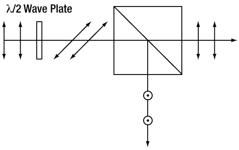
Figure 1. Normal Variable Beamsplitter Operation
The variable attenuation beamsplitter is a common component in many large optical systems and can serve as the basic building block for various applications just as; beam sampling, beam combining, beam splitting, power balance, and reflection isolation. Due to the modular design of the 30 mm cage cube system, this device can be easily integrated into a larger cage cube system. A variable attenuation beamsplitter can function at any wavelength supported by the optics of the system. For this application the optics were chosen for a 670 nm variable beamsplitter.
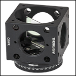
The polarization beamsplitting cube sits upon a B4CRP precision rotation platform and is held in place with a B6C cage cube clamp. The precision rotation platform allows for precise alignment of the polarization beamsplitting cube relative to the incident laser beam and also yields control over output beam alignment. This assembly is mounted within a C6WR 30 mm cage cube with ER cage rods attached to hold a half-wave plate and rotation mount. The rotation mount is a CRM1PT which is designed for integration into a 30 mm cage system. The precision control over the rotation is particularly useful when attempting to maximize or minimize a beam throughput. The zero-order mounted half-wave plate threads directly onto this rotation mount.
Cage System Overview
The Cage Assembly System provides a convenient way to construct large optomechanical systems with an established line of precision-machined building blocks designed for high flexibility and accurate alignment.
16 mm, 30 mm, and 60 mm Cage System Standards
Thorlabs offers three standards defined by the center-to-center spacing of the cage assembly rods (see image below). The 16 mm cage, 30 mm cage, and 60 mm cage standards are designed to accommodate Ø1/2", Ø1", and Ø2" optics, respectively. Specialized cage plates that allow smaller optics to be directly inserted into our larger cage systems are also available.
Standard Threads
The flexibility of our Cage Assembly System stems from well-defined mounting and thread standards designed to directly interface with a wide range of specialized products. The three most prevalent thread standards are our SM05 Series (0.535"-40 thread), SM1 Series (1.035"-40 thread), and SM2 Series (2.035"-40 thread), all of which were defined to house the industry's most common optic sizes. Essential building blocks, such as our popular lens tubes, directly interface to these standards.

An example of the standard cage plate measurements determining cage system compatibility.
| Standard Cage System Measurements | |||
|---|---|---|---|
| Cage System | 16 mm | 30 mm | 60 mm |
| Thread Series | SM05 | SM1 | SM2 |
| Rod to Rod Spacing | 16 mm (0.63") | 30 mm (1.18") | 60 mm (2.36") |
| Total Length | 25 mm (0.98") | 41 mm (1.60") | 71.1 mm (2.80") |
| Cage Components | ||
|---|---|---|
| Cage Rods | 16 mm | These rods are used to connect cage plates, optic mounts, and other components in the cage system. The SR Series Cage Rods are compatible with our 16 mm cage systems, while the 30 mm and 60 mm cage systems use ER Series Cage Rods. |
| 30 mm | ||
| 60 mm | ||
| Cage Plates | 16 mm | These serve as the basic building blocks for a cage system. They may have SM-threaded central bores, smooth bores sized for industry standard optics or to accommodate the outer profile of our SM Series Lens Tubes, or specialized bores for other components such as our FiberPorts. |
| 30 mm | ||
| 60 mm | ||
| Optic Mounts | 16 mm | Thorlabs offers fixed, kinematic, rotation, and translation mounts specifically designed for our Cage Systems. |
| 30 mm | ||
| 60 mm | ||
| Cage Cubes | 16 mm | These cubes are useful for housing larger optical components, such as prisms or mirrors, or optics that need to sit at an angle to the beam path, such as beamsplitters. Our cage cubes are available empty or with pre-mounted optics. |
| 30 mm | ||
| 60 mm | ||
| Replacement Setscrews | Replacement setscrews are offered for our 16 mm (SS4B013, SS4B025, and SS4B038) and 30 mm (SS4MS5 and SS4MS4) cage systems products. | |
| Post and Breadboard Mounts and Adapters | Mounting options for cage systems can be found on our Cage System Construction pages. Cage Systems can be mounted either parallel or perpendicular to the table surface. | |
| Size Adapters | Cage System Size Adapters can be used to integrate components from different cage system and threading standards. | |
| Specialized Components | Thorlabs also produces specialized cage components, such as Filter Wheels, a HeNe Laser Mount, and a FiberPort Cage Plate Adapter, allowing a wide range of our products to be integrated into cage-mounted optical systems. Explore our Cage Systems Visual Navigation Guide to see the full range of Thorlabs' cage components. | |
| Posted Comments: | |
Conner Phillips
(posted 2023-11-01 15:06:47.577) Greetings,
Is there a straightforward way mount a right angle prism mirror in a C6WR for simple 90 degree turning? I was hoping for a pre-aligned option like the CCM1-4ER/M, but don't see anything suitable. cdolbashian
(posted 2023-11-08 12:57:25.0) Thank you for reaching out to us with this inquiry. While we do not have something directly comparable, I have reached out to you directly to share what options we do have which would achieve much the same result. user
(posted 2023-02-19 16:50:14.14) Hi,
We are using a C4W 4-way mounting cage, which is very useful for mounting thin film samples in spectroscopy experiments. But we would also like to quickly switch to standard cuvette experiments in between. Just putting the cuvette in the middle of the C4W is possible, but not the best solution regarding stability and stray light. Can Thorlabs provide a matching anodized cuvette holder inset for the C4W (so one can operate the C4W in the same way as the CVH100/M cuvette holder)? Of course, we can manufacture such an inset in our machine shop, but it would be more convenient just to buy it at a reasonable price at Thorlabs. cdolbashian
(posted 2023-04-03 11:53:19.0) Thank you for reaching out to us with this inquiry. While we do not have a simple, direct, solution to your problem, we do have some potential workarounds to reach the solution you seek. I have contacted you directly to discuss such a solution. wentao yu
(posted 2019-09-23 00:57:17.69) it seems the solidwork file has something wrong, cause holes on each side are all clear holes without threads YLohia
(posted 2019-09-24 10:04:58.0) Hello, we only use cosmetic threads on the Solidworks files to save on service space and easy mating of different components. user
(posted 2017-05-05 12:18:24.97) can the sm1 lens tubes be directly connected to the c6w cube tcampbell
(posted 2017-05-05 12:49:12.0) Response from Tim at Thorlabs: Hello, thank you for contacting Thorlabs. Yes, each side face of the C6W cage cube has an SM1-threaded hole. user
(posted 2017-01-12 14:58:11.953) I would like to use 3-Axis NanoMax Flexure Stages MAX311D/M and two C4W cubes to build a double layer (high/low) optical path inverted microscope, one path for illumination, the other one for detection. I found that C4W-CC can connect two C4W cubes, however it will block the threads used for cage rods, is it possible manufacture a product of two C4W cubes as a whole? tfrisch
(posted 2017-01-12 09:22:40.0) Hello, thank you for your feedback. The simplest way to connect two cubes without using the threads on adjacent faces would be to use 4pcs of ERSCA and 4pcs of ER025. This would put a gap of about 0.3" between the cubes. If your application requires the cubes to be flush, please contact us at TechSupport@Thorlabs.com to discuss further options. aklossek
(posted 2014-10-21 08:29:37.237) Dear ladies and gentlemen,
I´m a little confused. I want to connect a CM1-DCH/M dichroic cage cube to a C4W cube. Which cube connector is needed the CM1-CC or the C4W-CC?
Best regards
André Klossek besembeson
(posted 2014-10-23 10:48:16.0) Response from Bweh: Both adapters CM1-CC or C4W-CC are possible to connect these cubes. The choice depends on the question: if and where you would like to attach further cage rods like ER2, ER3 etc (http://www.thorlabs.de/newgrouppage9.cfm?objectgroup_id=4125&pn=ER2) onto these cubes.
The countersunk holes on the C4W-CC is used to embrace the cube C4W. Screws are inserted and this adapter is connected to the cube. These screws go into the threaded holes which are normally used for the cage rods on this side of C4W. If you like to use rods there, then you should use the CM1-CC instead. This one will block the threads on the other cube CM1-DCH/M.
Looking at these links might also help with the visualization.
http://www.thorlabs.com/thorcat/22900/C4W-CC-AutoCADPDF.pdf
http://www.thorlabs.com/thorcat/19100/CM1-CC-AutoCADPDF.pdf cdaly
(posted 2012-11-27 13:43:00.0) Response from Chris at Thorlabs: At the moment, the B3C and B3RC are both the best options to be used with the B5C. They will need to be aligned manually however in order to attain the 45 degree AOI. Both will be able to achieve the orientation and can be locked in place once this is done, but the B3RC will perhaps make it a bit easier to do so, as this can be adjusted even after the mounting screws have been tightened down. farrell
(posted 2012-11-21 00:37:20.107) Dear Tim. Thank you for pointing out how best to mount the inside the cage. Do you have any suggestion as how to fix the angle of the B5C at exactly 45 deg. inside the cage? Is the best option the B3C or B3CR platform? farrell
(posted 2012-11-19 00:38:52.85) Hello Thorlabs, I wish to mount a WG41050 + B5C to make a 10/90 ratio beam-splitter (broadband non-polarising), at 45 degrees inside a 30mm cage. The cube platform B3C is rotatable. However, because I want exactly 45 degrees is it possible to purchase a fixed non-rotatable base plate? tcohen
(posted 2012-07-12 12:06:00.0) Response from Tim at Thorlabs: The B5C is designed for 1” (25.4mm optics). However, I have successfully mounted 25.0mm optics in these before. Please see the CAD drawing by clicking the red document icon next to the part number for exact details. The clear aperture is 24.1mm and a 25.0mm will not fall through. Although the included screws are most suited for gripping 25.4mm optics, 25.0mm optics can be securely mounted. kvasnicka
(posted 2012-07-12 09:38:17.0) Hello, can you please tell me if 25.0 mm diameter optic can be held by B5C or if it will fall through the hole? The B5C description says it is designed for 25.4 mm optic. Thank you. tcohen
(posted 2012-05-31 10:38:00.0) Response from Tim at Thorlabs: Thank you for your feedback. We would be more than happy to provide you with extra and I have contacted you directly to do so. christopher.artlett
(posted 2012-05-29 20:23:11.0) Hi, I am looking for more of the button-head 4-40 imperial screws supplied with the CM1-CC cage cube connectors. I'm using 30mm prism cage cubes in light-sensitive experiments and I would like to fill out the unused holes to minimise background light. Unfortunately screws of this type with the appropriate length are very hard to find. Thorlabs also do not appear to sell them separately. Can you suggest a source for these or provide them directly? bdada
(posted 2012-01-27 01:56:00.0) Response from Buki at Thorlabs:
Yes, we now have cage products for mounting dichroic filters. To mount a dichroic filter in the 30mm cube, place the filter in the FFM1 Cage Compatible Dichroic Filter Mount and then place the FFM1 on top of the B3C or B4C rotatable platform, which mounts to the C4W cube. You can close off the sides of the cubes with either the B1C or B2C cover plates.
All of these components can be found at the page linked below. Please contact TechSupport@thorlabs.com if you have additional questions.
http://www.thorlabs.com/NewGroupPage9.cfm?ObjectGroup_ID=3929. seamus.holden
(posted 2012-01-13 16:34:47.0) Hi, I would ideally like to mount a 25.5x36mm dichroic in the CM1 cube, primarily because I think such a mounting geometry would allow more repeatable alignment on swapping dichroics. I see such a product was discussed here in late 2009, is it now possible to buy such an item? Thanks, Seamus bdada
(posted 2011-10-12 16:19:00.0) Response from Buki at Thorlabs:
Thank you for your inquiry regarding the cage mount system. There are several options for building a periscope with the cage system. You could use the right angle kinematic mirror mount (KCB1) or the C4W cage cube with a mirror at a 45 degree angle using a B5C optic mount and B3C rotatable bottom plate. We have contacted you to discuss your application and assist you in selecting the appropriate components. auyeung
(posted 2011-10-06 19:40:47.0) Any way the C4W cube or the right angle cage mount be adapted so it can be used in a stable periscope configuration ? i.e. need to deflect the beam out of the plane of the table and keep the optics enclosed. (since mirrors facing up are prone to attract dust) jjurado
(posted 2011-07-06 16:15:00.0) Response from Javier at Thorlabs to kaccieli: Thank you very much for contacting us! The FM03 mirror can be easily bent due to its small thickness of 1 mm, causing the distortions that you are seeing. In this particular case, I would suggest gluing the mirror onto the holder; this would provide a strong support to the optic, without causing any distortions in the output profile. We offer a variety of optical adhesives, one of which is the NOA61:
http://www.thorlabs.com/NewGroupPage9.cfm?ObjectGroup_ID=196&pn=NOA61#196
I will contact you directly for further support. kaccieli
(posted 2011-07-06 18:07:27.0) I have mounted a cold mirror (FM03) onto a cage cube optical mount (B5C) and have observed that locking the plastic screw in place really deforms the mirrors surface. I have a very nicely collimated green laser beam according to the fringes on a shear plate but after the beam bounces off the cold mirror, the previously straight fringes become noticeably more wavy and its quite problematic. Tightening the screws a little more makes the fringe pattern even worse but the mounting must be secure. Any suggestions for alternatives? apalmentieri
(posted 2010-01-06 11:32:05.0) A response from Adam at Thorlabs to plane: The FFM1 is designed to be centered around a 1mm thick filter. The reflected beam will not be centered on the mechanical axis. It will be shifted by 1/2mm. Assuming a 1mm thick filter and ~refractive index of 1.5, the transmitted beam will shifted off the mechanical axis by ~.7mm. plane
(posted 2009-11-26 17:14:27.0) I have a question about using the FFM1 to hold a dichroic at 45 deg in a C4W cube: Does the intersection of the two mechanical axes of the cube intersect on a face of the dichroic (put another way - does an on-axis beam going into the cube reflect out along the 2nd mechanical axis or is it displaced)? klee
(posted 2009-10-24 00:24:04.0) A response from Ken at Thorlabs to adrian.daerr: We do have plan to make a CM1 cube and holder to hold 25 x 36 mm dichroic filters at 45°. We are now finalizing the design and they should be available in the 1st quarter next year. For 1" round optic, maybe you can take a look at the KC45D too. adrian.daerr
(posted 2009-10-23 20:50:43.0) Hello,
are there any plans to provide an alternate base for the CM1-4ER/M that would accept rectangular plan filters instead of prisms, i.e. allow mounting of a dichroic 25x35x1mm filter at 45degres ?
Something along the lines of C4W+B3C+FFM1, but with the compacity of the CM1 cubes ?
Could even be interesting for round optics, for the moment the only 45deg SM1 mounting solution for these seems to be the KCB1 whose clear aperture is far from being 1"...
thanks in advance
Adrian |

- Designed for 30 mm Cage Systems
- Top and Bottom Faces Feature Ø1.75" (44.5 mm) Through Holes
- Sides have Four 4-40 Tapped Holes Around an SM1-Threaded Hole
- Compatible with Ø6 mm Cage Rods
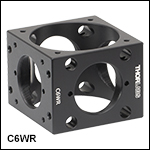
The C4W 30 mm Cage Cube offers four planar cube faces with 4-40 tapped holes, which directly accept cage rods, arranged around an SM1-threaded (1.035"-40) hole. The top and bottom faces of the cube are machined with a centrally located Ø1.75" (44.5 mm) hole surrounded by four 4-40 tapped holes designed for mounting our Cage Cube Plates and Platforms. Since this cube features tapped holes on all sides, it cannot be translated along cage rods. For applications that would require the ability to slide the cube along the cage rods, please consider the C6WR 30 mm Cage Cube featured below.
The C4W cage cube is compatible with a range of 30 mm Cage Components and Accessories, including port hole covers and cage cube platforms.

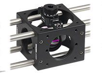
Click to Enlarge The CP360Q Quick-Release Mount for Ø1" Optics Being Used Within the C6WR Cube
- Designed for 30 mm Cage Systems
- Top and Bottom Faces Feature Ø1.75" (44.5 mm) Through Hole
- SM1-Threaded Hole Centered on Each Side Face
- Clearance Slots for Ø6 mm Cage Rods on Two Opposing Sides
- Four M4 Tapped Holes on Each of Other Two Opposing Sides
The C6WR 30 mm Cage Cube offers the same features as our C4W cage cube featured above except that it has two opposing faces with 4-40 tapped holes and two opposing faces with Ø6 mm through holes for mounting cage system rods centered on an SM1 (1.035"-40) threaded hole. The Ø6 mm through holes allow cage rods to pass through the cube, rather than be fastened to it. This feature allows the cube to be translated along the cage rods and then locked in place with the eight included M4 x 0.7 cage locking setscrews [5/64" (2.0 mm) hex]. The top and bottom faces of the cube are each machined with a centrally located Ø1.75" (44.5 mm) hole surrounded by four tapped holes designed for mounting our 30 mm Cage Cube Plates and Platforms.
This cage cube is compatible with a range of 30 mm Cage Components and Accessories, including port hole covers and cage cube platforms. Please note that the cage cube platforms will block the lower two cage rod holes of the C6WR unless mounted using the C6WA adapter plate.

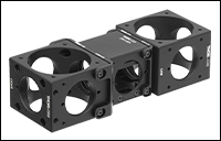
Click to Enlarge A C4W and C6WR Cage Cube connected to a 1.5" wide CCM1-4ER Compact Cage Cube using the C4W-CC and CM1-CC Cube Connectors, respectively.
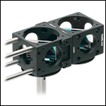
Click to Enlarge C4W-CC Connecting Two 2" Wide Cage Cubes
- C4W-CC: Connect Two 2" Wide Cage Cubes Side by Side
- Connect a 2" Wide Cage Cube to a 1.5" Wide Cage Cube
- Compatible with C4W and C6WR Cage Cubes
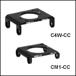
The C4W-CC cage cube connector allows our 2" wide 30 mm cage cubes to be connected together as shown in the image to the near-right. Our C4W and C6WR cubes are both compatible with this connector. Furthermore, the C4W-CC can be used to connect one of our 2" cubes to our 1.5" wide 30 mm cage cubes as seen in the far-right image.
We also offer the CM1-CC cube connector as another option for connecting 2" wide 30 mm cage cubes, such as our C4W or C6WR, to 1.5" wide 20 mm cage cubes.
Each cage cube connector comes with four 4-40 button-head screws, two 4-40 flat-head screws, four washers, and a 1/16" hex key.
Alignment Pins
Please note that these connectors require drilled holes on the cube face next to the SM1-threaded ports, as the cube connectors have alignment pins. If you have an older cube and would like it updated for free, please contact Technical Support. Alternatively, the alignment pins are press-fit inside their mounting holes and can be pressed out for use with un-drilled cubes.

- Highly Compressible Material Blocks Light Between Mating Optical Mounts
- Perfect for use with Light-Sensitive Instrumentation
- Typically used in a 30 mm Cage Assembly
This optical gasket is used to create a light-tight interface between two mating optical mounts. The highly compressible foam, measuring 0.25" (6 mm) thick in an uncompressed state, can easily adapt to uneven surfaces to maintain a light-tight seal between mating parts.
Most commonly used in cage assemblies, these gaskets are perfect for highly sensitive instrumentation such as CCD cameras and amplified photodiodes where ambient lighting is sufficient to saturate detection equipment or degrade signal-to-noise ratios.
 Products Home


 Zoom
Zoom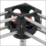

 30 mm Cage Cubes