Portable Optical Tweezers Educational Kit

- Designed for Education, Demonstration, and Classroom Use
- Easy-to-Use Kits Include Components Plus Free Educational Materials
EDU-OT3/M
Optical Tweezers Kit

Please Wait
Sample Microscope Video Captures Taken Using the Optical Tweezers Educational Kit to Trap 1 µm and 3 µm Beads
Optical Tweezers Educational Kit
- Designed for Educational, Demonstration, and Classroom Use
- Includes Extensive Manual for Easy Assembly and Use
- Choose from Educational Kits Containing Imperial or Metric Components
Educational Kit Details
- Experience the Fundamental Working Principles of an Optical Tweezers Setup
- Examine Brownian Motion and Trapping of Microbeads with a Visible Laser
- Demonstrate 3D Trapping of Microbeads with a Water and Cream Solution
- Portable without Readjustment
- Based on a Nobel Prize-Winning Experiment (Arthur Ashkin, 2018)
- Sample Preparation Kit Sold Separately Below
Optical tweezers, also known as optical traps, move and manipulate small particles using only a beam of light. A focused laser beam is used to exert forces on electrically uncharged particles with sizes from 1 to 10 µm, allowing the particles to be trapped, moved, and manipulated. This optical tweezers lab kit is optimized for classroom and lab use. It features an easy-to-construct optical path and sample positioning stage, a visible laser source, and a camera system for easy demonstration. The educational kit is assembled on a 30 cm x 60 cm (1' x 2') aluminum optical breadboard (included) and can be easily moved for demonstration purposes without needing realignment.
A sample preparation kit, available separately below, provides additional accessories for preparing samples that can be manipulated with the optical tweezers demonstration kit. The sample preparation kit is optimized for use with the Educational Kit.
Alternate Optical Tweezer Options
We also offer a highly configurable modular optical tweezers system for research and advanced graduate laboratories. For a comparison of the capabilities of our educational and modular tweezers options, please see the Comparison tab.
Thorlabs Educational Products
Thorlabs' educational line of products aims to promote physics, optics, and photonics by covering many classic experiments, as well as emerging fields of research. Each kit includes all the necessary components and a manual that contains both detailed setup instructions and extensive teaching materials. These educational lab kits are being offered at the price of the included components, with the educational materials offered for free. Technical support from our educational team is available both before and after purchase.
Purchasing Note: Both English and German language manuals/teaching information are available for this product. The imperial educational kit contains the English manual and US-style power cord. The appropriate manual and power cord will be included in the metric kit based on your shipping location. The power supplies and other electronic devices in both the metric and the imperial kit accept voltages from 100 to 230 VAC. Please contact Tech Support if you need a different language, cord style, or power supply. As with all products on our website, taxes are not included in the price shown below.
Laser Safety
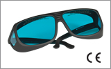
Thorlabs' Optical Tweezers Educational Kit uses a 658 nm, 40 mW Class 3B laser, which necessitates that all users be trained and follow all necessary safety protocols. This includes wearing the laser safety glasses included with the kit or an appropriate alternative. We would recommend discussing your needs with your organization's laser safety officer. More details about the laser classification system and Thorlabs laser safety products can be found on the Laser Safety tab.

Click to Enlarge
The Optical Tweezers Kit is mounted on a (1' x 2') 30 cm x 60 cm aluminum breadboard and can be moved without needing realignment. The screws and red outlines show the locations of mounted components.
Thorlabs educational optical tweezers kit is designed for classroom, lab, and other educational uses. It features a visible laser light source and an objective that does not require oil immersion. The CMOS viewing camera can be connected to a PC for demonstration use. The entire system is mounted on a 30 cm x 60 cm (1' x 2') aluminum breadboard and can be easily moved without needing realignment.
The EDU-OT3(/M) is an updated version of the EDU-OT2(/M) kit with several changes for improved performance and assembly. The camera was updated to the CS165CU(/M) Zelux® Color CMOS camera for improved imaging. The beamsplitter cube was replaced with the DMSP605R Dichroic Plate Beamsplitter to direct more laser power to the trap. Cage plates were updated to the latest versions with larger screws for more robust cage rod retention.
Laser and Microscope System
The EDU-OT3(/M) kit uses a L658P040 658 nm laser diode as the trap laser source. This 40 mW visible laser allows the spot to be easily observed through the microscope during operation for intuitive classroom demonstrations. The laser is focused through a Zeiss 63X, 0.8 NA objective, which also serves as the objective for the microscope. Sample illumination is accomplished using a previous generation MCWHL5 white LED, and the sample is viewed through a Thorlabs CS165CU(/M) Zelux Color CMOS camera. The laser, microscope, and optical path of the optical tweezers kit are shown below to the left.
Sample Positioning System
Samples are placed on the 3-axis sample positioning stage and moved around the static laser beam during experiments. The stage consists of two motorized MT1-Z9 (MT1/M-Z9) 12 mm travel translation stages for X- and Y-axis travel, plus a manual MT1B (MT1B/M) stage for Z-axis translation. The motorized stages are controlled by KDC101 servo motor controllers with customizable velocity settings. The sample positioning stage is shown below and to the right.

Click to Enlarge
Microscope and Camera Assembly with Beam Paths (Sample Stage not Shown)

Click to Enlarge
Sample Positioning Stage
Vertical Adjuster Screw Provides 150 µm Travel per Revolution
| EDU-OT3(/M) Optical Tweezers Kit Specifications | |
|---|---|
| Trap Laser Type | Diode |
| Trap Laser Wavelength (Typical) | 658 nm |
| Trap Laser Power (Typical) | 40 mW |
| Complete Trap Laser Specifications | |
| Objective NA | 0.8 |
| Working Distance | 0.3 mm |
| Camera | CS165CU(/M) CMOS Camera |
| Camera Resolution | 1440 x 1080 Pixels |
Optical Tweezers Operation
Optical traps can be characterized by two essential forces: the scattering force and the gradient force. The scattering force can be attributed to the principle of radiation pressure. Since the incoming laser light is partly absorbed and/or reflected by the particles, a momentum transfer occurs, which makes the particles move away from the light source. Thus, the scattering force increases with the laser power.
The second, more important force is the gradient force. If the laser beam acts on particles with a higher refractive index than the aqueous medium in which they are dispersed, they travel in the direction of maximal light intensity, allowing the particles to be trapped in the laser focus. If the laser is tightly focused, the gradient force can exceed the scattering force so that the particles can be trapped and moved in all three spatial dimensions.
For experimental purposes, microscopic glass or plastic beads (about 1 to 10 µm) or various other objects are dispersed in liquid (water, alcohol) on a glass slide. The particles can then be moved and manipulated by trapping them in the focused laser beam and moving the slide, which is attached to a positioning stage. The objective, CMOS camera, and an additional tube lens compose a microscope, which allows for the observation of the trapping procedure on the PC monitor. Various experiments can be performed with this setup, including trapping of particles with varying laser powers (up to 40 mW), evaluation of the effective viscosity of the dispersion via Brownian motion, determination of the optical trapping forces and their harmonic potential, and statistical analysis of the probability of the presence of the particles in the trap.
Laser Safety Information
The class 3B laser diode used in this kit emits up to 42 mW of optical power, which can cause damage to the eyes if viewed directly. The laser driver is equipped with a key switch and safety interlock, which should be used appropriately to avoid injury. Additionally, we recommend wearing appropriate laser safety glasses when using this kit. See the Laser Safety tab for details.
The Optical Tweezers Kit Used to Trap and Manipulate Various Particles Including 1 µm and 3 µm Beads and Large Starch and Fat Particles
To engage students, it is particularly helpful to point out that this kit is based on a Nobel prize-winning experiment! 48 years after publishing his paper (Ashkin A. "Acceleration and Trapping of Particles by Radiation Pressure." Physical Review Letters. 1970 January 26; 24: 156.), Arthur Ashkin was awarded the Nobel prize "for the optical tweezers and their application to biological systems". This emphasizes the profound meaning this technology has in fundamental research.
Several experiments that students can undertake as part of a lab course are outlined below. In addition to these exercises, the manual contains instructions for more activities such as adjusting the setup, finding the correct focus plane for the camera and laser, and arranging trapped particles within a sample.
Sample Preparation
Samples for the optical tweezers kit are simple to prepare. A sample containing 1 µm or 3 µm glass beads is useful, as these are well-suited for getting to know the operation and handling of the optical tweezers. Alternatively, an emulsion of cream in water will also produce particles that can be captured with the optical tweezers kit.
The following materials are necessary to create the sample:
- Microscope Slide with 20 µm Deep Wells
- Cover Glass
- Watch Glass Dish
- Pipette
- Sample Solution:
- Solution with Glass (Fused Silica) Beads and Distilled Water
- Cream and Water Emulsion
First, place a drop of the solution with the particles in the watch glass dish and combine with sufficient distilled water. Place this mixture in a well on the microscope slide using a pipette. Put a cover glass over the sample so that there are no air bubbles between the glass and the sample.
The samples can either be prepared before each experiment or they can be sealed between the slide and the cover glass with a UV adhesive. We recommend allowing students to prepare new samples as an educational exercise.
The OTKBTK sample preparation kit, available below, contains additional accessories that can be used to prepare samples for this optical tweezers kit.

Click to Enlarge

Click to Enlarge
After the laser is turned off, the particle of fat moves back to the surface of the emulsion.

Click to Enlarge

Click to Enlarge
A particle of cream is held at the focus of the laser underneath the surface of the emulsion.

Click to Enlarge

Click to Enlarge
The laser focus pushes down one of the cream particles floating at the surface of the emulsion.
Manipulation of a Cream Particle within a Cream Water Emulsion
Particles of dairy cream in a cream water emulsion are an appropriate size to be trapped by the optical tweezers in this kit. A sample can be created by mixing a drop of dairy cream with enough water to create a solution that is slightly milky in appearance. If one attempts to trap the cream particles with the laser, they will disappear from the focus and can no longer be clearly seen on the monitor (see the image to the right). The observation can be explained by the composition of the cream/water emulsion. Cream consists primarily of fat, which collects on the surface when mixed with water. The cream particles are therefore located on the surface of the water. However, the laser focus is located at a deeper level: when the cream particles are trapped, they are pulled down into the emulsion. This effect can be observed when the particle at which the laser is directed is tracked by adjusting the height of the stage as the particle moves deeper into the solution.
After the cream particle located in the optical trap has been brought into focus and can clearly be seen on the monitor, the laser can be switched off and the particle observed. Since the cream particle is not held in place by an optical trap after the laser is switched off, it will move upward once again to the surface of the water. Again, the motion of the particle can be tracked by adjusting the height of the stage.
Brownian Motion

Click to Enlarge
A sketch illustrating Brownian motion.

Click to Enlarge
The mean squared displacement for different sizes of glass beads is shown in the graph above.
Brownian motion is the random motion (translation and rotation) of microscopic free particles suspended in a fluid resulting from their collisions with the atoms or molecules of the fluid. Under the microscope, the paths of particles are seen as short, straight lines (see the figure to the right). The Brownian motion can be observed in experiments using the optical tweezers. The glass beads are located in a medium that consists of molecules that are constantly moving in all directions. Because of this, the molecules repeatedly bump into the beads, which causes a vibrating motion of the beads that can be observed under the optical tweezers. The higher the temperature, the more the molecules move.
Use a sample with the 3 µm glass spheres. You must first switch the laser off so that you can observe only Brownian motion. For evaluation, a video sequence with a duration of 2 minutes or more must be recorded. During this period, about 5 particles, which do not touch each other, should be in the image. A similar video should be recorded with the 1 µm spheres. The videos can be evaluated with the aid of image analysis software, which provides the x and y position of a particle over time (see the manual for a recommendation for a free software package).
We recommend evaluating and graphing the data obtained with the aid of a table calculation program. First, the mean squared displacement of the beads must be determined. This can be calculated from the positions of the beads (xi (ti ),yi (ti )) at different times, ti, which can be measured from the video:

The mean position value up to each time tn can be calculated by averaging all of the measured position values over time. To eliminate statistically possible deviations of individual particles, the mean value should also be averaged over M particles:

We recommend using at least 5 particles for this calculation. The values obtained for the average squared displacement, <r ²>(t n), with respect to time for three sizes of glass beads are plotted in the graph to the right. Note that the slope of the lines decreases with increasing diameter of the beads, meaning that larger beads move less. This result can easily be explained by Brownian motion: the 1 µm spheres can be more easily set into motion by impact with the water molecules than larger spheres. Therefore, a 1 µm bead travels more in a certain time interval than a larger bead.
Maximum Holding Force of the Optical Trap
Frictional forces from the surrounding liquid will act on the individual glass beads moving through the solution with velocity, v, and inhibit their motion. This force is proportional to the bead size and the viscosity of the fluid:

Here, R describes the radius of the bead. The viscosity, ηeff, describes how "thick" the combination of water and beads is, which means it is different for each sample. It can be calculated from the mean squared displacement of particles in the fluid, which was experimentally determined in the Brownian Motion experiment described above. The slope, m, of the line describing the beam squared displacement is related to the viscosity by the following equation:

where ηeff denotes the effective viscosity, R is the radius of the bead, and T is the temperature of the sample in Kelvin, and k B is the Boltzmann constant, which has an approximate value of 1.38 x 10²³ J/K. The effective viscosity should be on the order of 10-3 N s/m².
If the bead is in the optical trap, two forces act on it. First, the frictional force, F R, which is caused by the suspension in which the glass bead is located, and the holding force, F H, of the optical trap. The maximum holding force is defined as the force needed to maintain a speed v max at which the bead can just be held by the trap. This is the case where the maximum holding force and frictional force are in balance:

For the EDU-OT3(/M), the holding force will typically be on the order of several pN, dependent on the contrast in refractive index between the trapped particle and the surrounding liquid.
Portable Optical Tweezers Kit Components

Thorlabs' Optical Tweezers Educational Kits are available in imperial and metric versions. In cases where the metric and imperial kits contain parts with different item numbers, metric part numbers and measurements are indicated by parentheses unless otherwise noted.
| Item # | Description | Qty. |
|---|---|---|
| Trapping Laser Source | ||
| SR9A-DB9 | ESD Protection and Strain Relief Cable | 1 |
| L658P040a | 658 nm, 40 mW Laser Diode | 1 |
| LTN330-A | Adjustable Collimator for Ø5.6 mm Laser Diodes | 1 |
| KLD101 | K-Cube™ Laser Diode Driver | 1 |
| TPS002 | Laser Diode Driver Power Supply | 1 |
| RS3.5P8E (RS3.5P4M) | Ø1" (Ø25 mm) Pedestal Post, 3" (90 mm) Tall | 1 |
| CF125 | Clamping Fork | 1 |
| KC1-T(/M)b | Tip/Tilt Cage Mount | 1 |
| AD15F | SM1-Threaded Adapter for Ø15 mm Components | 1 |
| Beam Expander | ||
| ER1 | Ø6 mm Cage Rod, 1" Long | 2 |
| ER3 | Ø6 mm Cage Rod, 3" Long | 2 |
| ER6 | Ø6 mm Cage Rod, 6" Long | 2 |
| ER10 | Ø6 mm Cage Rod, 10" Long | 2 |
| CP45(/M) | 30 mm Removable Segment Cage Plate | 2 |
| CP45T(/M) | 30 mm Removable Segment Cage Plate, Thick | 2 |
| LA1074-A | Ø1/2" Plano-Convex Lens, f = 20 mm | 1 |
| LA1509-A | Ø1" Plano-Convex Lens, f = 100 mm | 1 |
| SM1A6 | SM05 to SM1 Adapter | 1 |
| SM05L03 | SM05 Lens Tube, 0.3" Long | 1 |
| TR3 (TR75/M) | Ø1/2" (Ø12.7 mm) Post, 3" (75 mm) Long | 1 |
| PH3 (PH75/M) | Ø1/2" (Ø12.7 mm) Post Holder, 3" (75 mm) Long | 1 |
| CF125 | Clamping Fork | 1 |
| BE1 (BE1/M) | Pedestal Base Adapter | 1 |
| Sample Positioning System | ||
| MT1-Z9 (MT1/M-Z9) | Motorized Translation Stage, 1/2" (12 mm) Travel | 2 |
| MT1B (MT1B/M) | Manual Translation Stage, 1/2" (13 mm) Travel | 1 |
| KDC101 | K-Cube™ DC Servo Motor Controller | 2 |
| KPS201c | 15 V Power Supply | 2 |
| MT402 | Right Angle Bracket | 1 |
| MT405 | Side-Mounted Actuator Adapter | 2 |
| - | Slide Holder Part 1 | 1 |
| - | Slide Holder Part 2 | 1 |
| MT401 (MT401/M) | Mounting Base for Translation Stages | 1 |
| Right-Angle Mirrors | ||
| KCB1C(/M) | Right Angle Kinematic Mirror Mount | 2 |
| PF10-03-P01 | Ø1" Protected Silver Mirror | 2 |
| SM1L05 | Ø1" Lens Tube, 0.5" Long | 2 |
| SM1L10 | Ø1" Lens Tube, 1" Long | 2 |
| SM1CPL10 | SM1 Lens Tube Coupler | 2 |
| Item # | Description | Qty. |
|---|---|---|
| Microscope | ||
| CS165CU(/M) | Zelux® 1.6 MP Color CMOS Camera | 1 |
| SM1T2 | SM1 Lens Tube Coupler | 2 |
| SM1NT1 | SM1 Locking Ring | 1 |
| C1498 (C1498/M) | Ø1.5" Post Clamp | 3 |
| SM1L15 | SM1 Lens Tube, 1.5" Long | 1 |
| CP33(/M) | SM1-Threaded Cage Plate | 4 |
| CP33T(/M) | Thick SM1-Threaded Cage Plate | 1 |
| SPT1C(/M) | XY Slip Plate Positioner | 1 |
| CM1-DCH(/M) | 30 mm Cage Cube with Dichroic Filter Mount | 1 |
| DMSP605R | 25 mm x 36 mm Shortpass Dichroic Mirror, 605 nm Cutoff | 1 |
| FES0650a | Ø1" Shortpass Filter, 650 nm Cut Off | 1 |
| LB1676 | Ø1" Bi-Convex Lens, f = 100 mm | 1 |
| SM1CP2 | SM1 End Cap | 1 |
| DP14A(/M) | Ø1.5" Damped Mounting Post | 1 |
| ER05 | Ø6 mm Cage Rod, 0.5" Long | 4 |
| ER1.5 | Ø6 mm Cage Rod, 1.5" Long | 4 |
| ER3 | Ø6 mm Cage Rod, 3" Long | 4 |
| MCWHL7 | Cold White Mounted LED | 1 |
| LEDD1B | T-Cube™ LED Driver | 1 |
| KPS201b | 15 V Power Supply | 1 |
| SM1L10 | SM1 Lens Tube, 1" Long | 1 |
| DG10-600 | Ø1" N-BK7 Ground Glass Diffuser | 1 |
| - | Zeiss Microscope Objective, 63X, 0.8 NA | 1 |
| SM1A17 | M27 x 0.75 to SM1 Adapter | 1 |
| Additional Components | ||
| MB1224 (MB3060/M) | Aluminum Breadboard, 1' x 2' (30 cm x 60 cm) | 1 |
| RDF1 | Set of 4 Rubber Damping Breadboard Feet | 1 |
| SPW606 | SM1 Spanner Wrench, 1" Long | 1 |
| BBH1 | Set of 2 Breadboard Handles | 1 |
| CPA1 | Cage Alignment Plate | 1 |
| ADF1 | Fluorescent Alignment Disk, Blue | 1 |
| - | Laser Safety Glasses | 1 |
| - | Laser Alignment Glasses | 1 |
Imperial Kit: Included Hardware and Screws
| Item # | Description | Qty. | Item # | Description | Qty. |
|---|---|---|---|---|---|
| SPW502 | Spanner Wrench for Slotted SM1 Locking Rings |
1 | SH25S075a | 1/4"-20 Cap Screw, 3/4" Long |
4 |
| BD-5/64 | 5/64" Balldriver | 1 | SH8S038a | 8-32 Cap Screw, 3/8" Long |
2 |
| BD-3/16L | 3/16" Balldriver | 1 | SH8S050a | 8-32 Cap Screw, 1/2" Long |
3 |
| CCHK | Imperial Hex Key Set | 1 | SS8S050a | 8-32 Setscrew, 1/2" Long |
1 |
| - | 1/4"-20 Cap Screw, 0.315" Long |
2 | SD1 | 1/4" to #8 Counterbore Adapter, 10 Pack |
1 |
| SH25S038a | 1/4"-20 Cap Screw, 3/8" Long |
10 | - | #8 Washer | 2 |
| SH25S050a | 1/4"-20 Cap Screw, 1/2" Long |
12 | - | 1/4" Washer | 22 |
| SH25S063a | 1/4"-20 Cap Screw, 5/8" Long |
8 | - | 1/8" x 1/4" Steel Dowel Pin |
8 |
Metric Kit: Included Hardware and Screws
| Item # | Description | Qty. | Item # | Description | Qty. |
|---|---|---|---|---|---|
| SPW502 | Spanner Wrench for Slotted SM1 Locking Rings |
1 | SH6MS20a | M6 Cap Screw, 20 mm Long |
4 |
| BD-2M | 2 mm Balldriver | 1 | SH4MS10a | M4 Cap Screw, 10 mm Long |
2 |
| BD-5ML | 5 mm Balldriver | 1 | SH4MS12a | M4 Cap Screw, 12 mm Long |
3 |
| CCHK/M | Metric Hex Key Set | 1 | SS4MS12a | M4 Setscrew, 12 mm Long |
1 |
| - | M6 Cap Screw, 8 mm Long |
2 | SD1 | M6 to M4 Counterbore Adapter, 10 Pack |
1 |
| SH6MS10a | M6 Cap Screw, 10 mm Long |
10 | - | M4 Washer | 2 |
| SH6MS12a | M6 Cap Screw, 12 mm Long |
12 | - | M6 Washer | 22 |
| SH6MS16a | M6 Cap Screw, 16 mm Long |
8 | - | 1/8" x 1/4" Steel Dowel Pin |
8 |
Software Downloads
We recommend operating these optical tweezers using the ThorCam™ and Kinesis® software packages. A guide to software installation and settings can be found in the manual.
Thorlabs offers two different optical tweezers options: our open-architecture Modular System, which is designed for research and advanced teaching labs, and the Educational Kit featured on this page designed for introducing the basics of optical trapping. While our modular system and the demonstration kit look similar there are many key distinguishing features that are summarized in the table below.
| Educational Kit | Modular System | |
|---|---|---|
| Item # | EDU-OT3(/M) | OTKB(/M) |
| Laser Wavelength | 658 nm (Visible) | 976 nm (IR) |
| Laser Power | 40 mW | 300 mW |
| Objective Type | Air | Immersion |
| Positioning System | Servo Motor in XY; Manual in Z | Piezo Actuators and Strain Gauge in XYZ |
| Force Measurement | Camera Image Analyzed with Open Source Software | Back Focal Plane Detection via Position Sensing Detector (Optional) |
| Configuration | Upright | Inverted |
| Target Groups |
|
|
| Educational Aspects |
|
|
Laser Safety and Classification
Safe practices and proper usage of safety equipment should be taken into consideration when operating lasers. The eye is susceptible to injury, even from very low levels of laser light. Thorlabs offers a range of laser safety accessories that can be used to reduce the risk of accidents or injuries. Laser emission in the visible and near infrared spectral ranges has the greatest potential for retinal injury, as the cornea and lens are transparent to those wavelengths, and the lens can focus the laser energy onto the retina.
Safe Practices and Light Safety Accessories
- Laser safety eyewear must be worn whenever working with Class 3 or 4 lasers.
- Regardless of laser class, Thorlabs recommends the use of laser safety eyewear whenever working with laser beams with non-negligible powers, since metallic tools such as screwdrivers can accidentally redirect a beam.
- Laser goggles designed for specific wavelengths should be clearly available near laser setups to protect the wearer from unintentional laser reflections.
- Goggles are marked with the wavelength range over which protection is afforded and the minimum optical density within that range.
- Laser Safety Curtains and Laser Safety Fabric shield other parts of the lab from high energy lasers.
- Blackout Materials can prevent direct or reflected light from leaving the experimental setup area.
- Thorlabs' Enclosure Systems can be used to contain optical setups to isolate or minimize laser hazards.
- A fiber-pigtailed laser should always be turned off before connecting it to or disconnecting it from another fiber, especially when the laser is at power levels above 10 mW.
- All beams should be terminated at the edge of the table, and laboratory doors should be closed whenever a laser is in use.
- Do not place laser beams at eye level.
- Carry out experiments on an optical table such that all laser beams travel horizontally.
- Remove unnecessary reflective items such as reflective jewelry (e.g., rings, watches, etc.) while working near the beam path.
- Be aware that lenses and other optical devices may reflect a portion of the incident beam from the front or rear surface.
- Operate a laser at the minimum power necessary for any operation.
- If possible, reduce the output power of a laser during alignment procedures.
- Use beam shutters and filters to reduce the beam power.
- Post appropriate warning signs or labels near laser setups or rooms.
- Use a laser sign with a lightbox if operating Class 3R or 4 lasers (i.e., lasers requiring the use of a safety interlock).
- Do not use Laser Viewing Cards in place of a proper Beam Trap.
Laser Classification
Lasers are categorized into different classes according to their ability to cause eye and other damage. The International Electrotechnical Commission (IEC) is a global organization that prepares and publishes international standards for all electrical, electronic, and related technologies. The IEC document 60825-1 outlines the safety of laser products. A description of each class of laser is given below:
| Class | Description | Warning Label |
|---|---|---|
| 1 | This class of laser is safe under all conditions of normal use, including use with optical instruments for intrabeam viewing. Lasers in this class do not emit radiation at levels that may cause injury during normal operation, and therefore the maximum permissible exposure (MPE) cannot be exceeded. Class 1 lasers can also include enclosed, high-power lasers where exposure to the radiation is not possible without opening or shutting down the laser. |  |
| 1M | Class 1M lasers are safe except when used in conjunction with optical components such as telescopes and microscopes. Lasers belonging to this class emit large-diameter or divergent beams, and the MPE cannot normally be exceeded unless focusing or imaging optics are used to narrow the beam. However, if the beam is refocused, the hazard may be increased and the class may be changed accordingly. |  |
| 2 | Class 2 lasers, which are limited to 1 mW of visible continuous-wave radiation, are safe because the blink reflex will limit the exposure in the eye to 0.25 seconds. This category only applies to visible radiation (400 - 700 nm). |  |
| 2M | Because of the blink reflex, this class of laser is classified as safe as long as the beam is not viewed through optical instruments. This laser class also applies to larger-diameter or diverging laser beams. |  |
| 3R | Class 3R lasers produce visible and invisible light that is hazardous under direct and specular-reflection viewing conditions. Eye injuries may occur if you directly view the beam, especially when using optical instruments. Lasers in this class are considered safe as long as they are handled with restricted beam viewing. The MPE can be exceeded with this class of laser; however, this presents a low risk level to injury. Visible, continuous-wave lasers in this class are limited to 5 mW of output power. |  |
| 3B | Class 3B lasers are hazardous to the eye if exposed directly. Diffuse reflections are usually not harmful, but may be when using higher-power Class 3B lasers. Safe handling of devices in this class includes wearing protective eyewear where direct viewing of the laser beam may occur. Lasers of this class must be equipped with a key switch and a safety interlock; moreover, laser safety signs should be used, such that the laser cannot be used without the safety light turning on. Laser products with power output near the upper range of Class 3B may also cause skin burns. |  |
| 4 | This class of laser may cause damage to the skin, and also to the eye, even from the viewing of diffuse reflections. These hazards may also apply to indirect or non-specular reflections of the beam, even from apparently matte surfaces. Great care must be taken when handling these lasers. They also represent a fire risk, because they may ignite combustible material. Class 4 lasers must be equipped with a key switch and a safety interlock. |  |
| All class 2 lasers (and higher) must display, in addition to the corresponding sign above, this triangular warning sign. |  |
|
The Portable Optical Tweezers Educational Kit was developed in cooperation with Antje Bergmann and Daniela Rappa from the Karlsruhe Institute of Technology.
Do you have ideas for an experiment that you would like to see implemented in an educational kit? Contact us at techsupport@thorlabs.com; we'd love to hear from you.
| Posted Comments: | |
user
(posted 2023-02-13 17:07:13.12) Hello, have you perhaps tested the exercise in which the holding force of the optical tweezers is measured with the EDU-OT3/M kit? Do you have any hints regarding the easiest way to perform this experiment? GBoedecker
(posted 2023-02-15 03:08:59.0) Thank you for your feedback! Chapter 6.5 of the manual describes how to approximate the holding force. First, Brownian motion is investigated to deduce the effective viscosity of the bead solution. Then, a bead is trapped and moved, with increased speed. The maximum speed at which the bead is still held by the laser is used to calculate an approximate value for the holding force. Hongtao Chen
(posted 2022-09-14 14:55:28.0) - Slide Holder Part 1 1
- Slide Holder Part 2 1
What are the parts number of the slide holder?
It is very useful for us and I am interested in it.
Thanks mdiekmann
(posted 2022-09-16 03:40:59.0) Thank you for contacting us! These are not standard parts, so we cannot post a part number here, but we can offer them to you directly. You selected not to be contacted, but you are welcome to reach out to your local tech support team for a quote. Scott Handley
(posted 2022-07-27 09:43:24.307) Can I buy glass slides separately ... if so, what should I buy? Marcin Sleczka
(posted 2020-09-11 03:27:37.247) Dear Thorlabs Team,
Could you tell me where I can buy slide holder for this kit? I have bought separately most of the elements where slider holder I have replaced by MAX3SLH. I have problem to connected it with the XYZ stage right now.
Do you have any suggestion how to resolve this issue?
Best regards
Marcin Sleczka soswald
(posted 2020-09-11 08:17:57.0) Response from Sönke at Thorlabs: Dear Marcin, thank you for your feedback. We can provide the slide holder as custom items. I have reached out to you directly to discuss this further.
Please be aware that the kit price is always equal to the sum of the component prices, there is no extra charge when buying the kit as a whole. Jing Xu
(posted 2020-02-24 18:59:13.347) Hi,
We have the EDU-OT1 portable optical tweezer system for our junior lab class.
In this system, the LED light source does not go through a condenser lens (or similar) before reaching the sample plane. As a result, the LED light output is diverging as it reaches the sample plane.
Can you please help resolve this problem? The LED light needs to be at focus at the sample plane. Neither the manual nor the kit we have indicate how this focusing might take place.
Your input is very much appreciated.
Best,
Jing mdiekmann
(posted 2020-02-27 07:35:40.0) Jens Kuchenmeister: A response from Jens at Thorlabs to Jing: There are different illumination patterns for microscopes and the simplest is a divergent illumination. The ability of the setup to observe and trap particles is not negatively affected by this simple illumination pattern. Carlos Luna
(posted 2019-03-28 19:52:15.347) I am very interested in this Portable Optical Tweezers Educational Kit. However, I would like to use this set up for quantitative differential phase contrast. So, I want to use this setup more like a highly reconfigurable digital microscope for which I do not need the laser part of this kit.
I would like to kindly ask you to help me tailor a kit for my specific needs.
Relevant paper:
Michael Chen, Zachary F. Phillips, and Laura Waller, “Quantitative differential phase contrast (DPC) microscopy with computational aberration correction,” Opt. Express 26, 32888-32899 (2018)
Please let me know if you need more details. I look forward to hear from you.
Kind regards,
Carlos Luna
jcrl.luna@gmail.com
Science and Research 1
University of Houston
TX nreusch
(posted 2019-04-02 06:03:42.0) This is a response from Nicola at Thorlabs. Thank you for your inquiry! We will get back to you directly to discuss your specific application. |

- Complete Photonics Kit Includes All Hardware and Tools (Computer Not Included)
- Includes Extensive Manual for Easy Assembly and Use
- Sample Preparation Kit Optimized for Use with Optical Tweezers Sold Separately Below
Thorlabs' EDU-OT3(/M) Optical Tweezers Educational Kit includes the components to build optical tweezers (also known as an optical trap). It features an easy-to-construct optical path and sample positioning stage, a visible laser source, and a camera system. The educational kit is assembled on a 30 cm x 60 cm (1' x 2') aluminum optical breadboard (included) and can be easily moved for demonstration purposes without needing realignment.
A sample preparation kit, available separately below, provides additional accessories for preparing samples that can be manipulated with the optical tweezers demonstration kit.

The OTKBTK is designed for use with our OTKB Modular Optical Tweezers and our EDU-OT3 Educational Discovery Kit. It allows users to quickly prepare a sample and test for optical trapping once they have completed construction. Included with the kit are the following:
- Non-Drying Immersion Oil for Microscopy, Cargille Type LDF
- Not for Use with EDU-OT3(/M)
- Non-Functionalized Fused Silica Beads in Deionized Water, Ø2.06 µm, 2 g/ml
- Mini Pipette with a 50 µL Volume
- Two Plastic Slides with Built-In Channel, 400 µm Height, 100 µL Volume
- 5 Microscope Glass Slides with Reaction Wells, Ø10 mm, 20 µm Deep
- 100 Pieces of 18 mm x 18 mm Cover Glass, No. 1.5 Thickness
- Dropper for Immersion Oil
 Products Home





 Zoom
Zoom


 Portable Optical Tweezers Kit