 Products Home / Lasers / Coherent Sources / Single-Frequency Lasers / Low-Noise, Narrow-Linewidth Turnkey Lasers / Low-Noise, Turnkey Laser Systems, 780 or 795 nm
Low-Noise, Turnkey Laser Systems, 780 or 795 nm
- High-Power, Turnkey, Single-Frequency Laser Systems
- Wavelengths Targeting Rb at 780 nm (D2) or 795 nm (D1)
- 2.4 nm Temperature Tuning Range
- >25 GHz DC Current Modulation Tuning Range
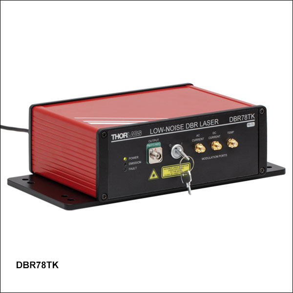
DBR78TK
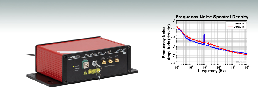
Low-Noise, Turnkey Laser System, 780 nm
The frequency noise spectral density gives a Lorentzian linewidth of 235 kHz for the DBR78TK Laser and 147 kHz for the DBR79TK Laser.


Please Wait
| Key Specifications | ||
|---|---|---|
| Item # | DBR78TK | DBR79TK |
| Center Wavelength | 780.2 nm | 794.8 nm |
| Output Powera,b | >30 mW | |
| Typical Linewidth | <400 kHz | |
| DC Current Tuning Range (Typical) | 39 GHz | 26 GHz |
| Typical RINc | -150 dBc/Hz | |
| Temperature Tuning Range | 2.4 nm | |
Applications
- Rubidium Cooling
- Rubidium Re-Pumping
- Neutral Atom Quantum Computing
- Rubidium Rydberg States
- Rubidium Spectroscopy
- SPDC Crystal Pumping
Features
- High-Power Turnkey Single-Frequency Laser Systems Targeting Rb Transitions
- Factory-Set to the Rb D2 (Item # DBR78TK) or D1 (Item # DBR79TK) Nominal Vacuum Transition
- Low-Noise Drive Electronics to Minimize RIN and Linewidth
- Analog Modulation Inputs for DC Current, AC Current, and Laser Temperature
- Integrated Isolator to Minimize Effects of Back-Reflected Light
- Remote Operation and Set-Point Adjustment with USB 2.0 Command-Line Interface
Click to Enlarge
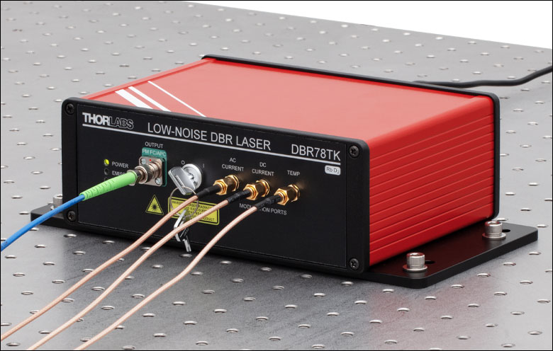
Figure 1.1 The DBR78TK and DBR79TK lasers can be mounted to an optical table using four 1/4" (M6) cap screws.
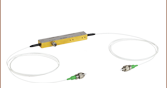
Thorlabs' DBR78TK and DBR79TK single-frequency, turnkey, low-noise laser systems integrate our DBR780PN or DBR795PN Distributed Bragg Reflector (DBR) laser diodes with a low-noise driver and temperature stabilization inside of a benchtop housing. To minimize the laser linewidth and relative intensity noise (RIN), these lasers include drive electronics that are designed to minimize the current noise. An isolator is integrated at the output of the lasers to minimize the impact of any back-reflected light on the lasers.
Each DBR system is factory-set with a drive current and temperature to provide over 30 mW of optical power at wavelengths corresponding to atomic transition lines of Rubidium. Each laser is shipped with a test data sheet taken at the preset operating conditions; click here for a sample data sheet. The wavelength and output power of these laser systems can also be tuned by adjusting the current or the temperature of the laser chip through either the analog ports on the front of the device or by sending a command through USB communication (see Remote Operation below). See the Graphs and Specs tabs for more information on current and temperature tuning of these lasers.
The optical outputs of these lasers are fiber-coupled via FC/APC bulkhead (2.0 mm narrow key) output connectors. For best performance, we recommend connecting our PM FC/APC fiber patch cables that contain PM780-HP fiber. Note that the polarization axis is aligned with the narrow key of the bulkhead connector.
The systems are powered by a 12 VDC, 4 A input. A DS12 power supply is provided with each laser; see the Shipping List tab for a complete list of items included with the device.
We also offer turnkey versions of our Distributed Feedback (DFB), and Ultra-Low-Noise (ULN) single-frequency laser diodes at 1310 nm and 1550 nm. A list of selected DBR, DFB, and ULN single-frequency laser diodes is available in the Contact Me box. For more information on the characteristics of these different types of single-frequency diodes, see the SFL Overview tab.
Remote Operation
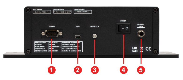
Remote operation is also possible by connecting the laser to a PC (not included) via the USB port or 9-pin D-sub connector for RS-485 communication protocol on the back of the unit and using a command line interface. In addition to basic functions such as turning the laser on and off or reading status indicators, the command line enables the user to modify the laser operating set-points. The full list of commands can be found in the laser manual. A USB-AB-72 USB 2.0 Type-A to Mini-B Cable is included with each device. A 9-Pin male D-Sub connector is also included on the back panel of the system for RS-485 communication protocol. Please refer to the Pin Diagrams tab for the pin assignment of the 9-pin D-sub connector.

Reza Salem
BU Leader, Fiber Lasers

I look forward to hearing from you!
Committed to Your Success
I am happy to assist with questions concerning our single-frequency, low-noise, turnkey laser systems. If our catalog offerings do not meet your needs, these products can be customized using some of our DBR and DFB single-frequency laser devices that require a drive current ≤1 A. Some of the possible (wavelengths / incorporated laser) combinations available for our turnkey systems are:If you are interested in these laser systems, I invite you to contact us with your questions, comments, or requests.
Applications
These lasers are designed with laser frequency locking applications in mind and can be used with our Saturated Absorption Spectroscopy System, as well as a Dichroic Atomic Vapor Spectroscopy Kit. In laser frequency locking, a frequency-tunable diode laser is split into counter-propagating pump and probe beams through a rubidium vapor reference cell. This technique isolates narrow hyperfine transitions, known as Lamb dips, within the broader Doppler-broadened absorption profile, providing sharp error signals for laser frequency stabilization. By combining these lasers with modulation and feedback electronics, such as the DSC1 Digital Servo Controller and the PDB210A Balanced Photodetector, one can achieve robust, long-term frequency locking to the atomic transitions - an essential requirement for applications such as atomic clocks, laser cooling, and quantum sensing.
These lasers can also be used to pump our BBO and PPKTP crystals to achieve Spontaneous Parametric Down Conversion (SPDC) to produce polarization-entangled photon pairs or heralded single photons.
| Item # | DBR78TK | DBR79TK |
|---|---|---|
| Laser Specificationsa | ||
| Center Wavelengthb | 780.2 nm | 794.8 nm |
| Output Powerc,d | >30 mW | |
| Linewidthe | <400 kHz | |
| DC Current Modulation Tuning Range (Typical) | 39 GHz | 26 GHz |
| Relative Intensity Noise (RIN)f | -150 dBc/Hz | |
| Side-Mode Suppression Ratio (SMSR) | >30 dB (Typ. 50 dB) | |
| Polarization Extinction Ratio (PER) | >16 dB | |
| Output Isolation | >25 dB | |
| Threshold Current | 30 mA (Typ. 45 mA) | |
| Current Tuning Coefficient | 0.002 nm/mA | 0.0014 nm/mA |
| Temperature Tuning | 0.06 nm/°C | |
| Slope Efficiency | 0.25 W/A | |
| Temperature Tuning Range | 2.4 nm | |
| Fiber Specifications | ||
| Output Fiber Typeg | PM780-HP | |
| Output Fiber Connectors | FC/APC Compatible, 2.0 mm Narrow Key | |
| External Modulation Specifications | ||
| Current Modulation Rate (AC and DC) | 2 mA/V (AC), 4 mA/V (DC) | |
| Temperature Modulation Rate | Firmware Adjustable (Default = 0.2 °C/V) | |
| External Voltage Range (All Modulation Ports) | -5 V to 5 V | |
| Input Impedance (All Modulation Ports) | 1 kΩ | |
| AC Current Modulation Frequency Range | 2 kHz to 20 MHz | |
| DC Current Modulation Frequency Range | DC to 5 MHz | |
| Temperature Modulation Bandwidth | 1 Hz | |
| Absolute Maximum Ratings | ||
|---|---|---|
| Item # | DBR78TK | DBR79TK |
| Absolute Maximum Output Power | 45 mW | |
| Operating Chip Temperature | 5 °C to 45 °C | |
| Storage Temperature | -10 °C to 65 °C | |
| General Specifications | ||
|---|---|---|
| Item # | DBR78TK | DBR79TK |
| Input Voltage | 12 V (from DS12 Power Supply) | |
| Input Power | 20 W (Max) | |
| Dimensions (W x D x H) | 10.00" x 5.31" x 2.93" (254.0 mm x 135.0 mm x 74.4 mm) |
|
| Weight | 4.7 lbs (2.1 kg) | |
| Laser Class | 3B | |
Figures 3.1 and 3.2 represent the relative intensity noise (RIN) and frequency noise for these low-noise, single-frequency laser systems.
Click to Enlarge
Figure 3.2 Example frequency noise data for the DBR78TK and DBR79TK laser systems operated at the factory-set conditions.
Click to Enlarge
Figure 3.1 The typical low-frequency relative intensity noise (RIN) for DBR78TK and DBR79TK laser systems operated at the factory-set conditions. This measurment is limited by the noise floor at frequencies above 100 kHz
Figures 3.3 and 3.4 represent the typical performance of the DBR78TK and DBR79TK low-noise laser systems. Specific performance data is provided on the datasheet shipped with each device; click here for a sample data sheet.
Click to Enlarge
Click Here for Data
Figure 3.3 Example output power vs. current data for a DBR78TK laser system operated at factory-set conditions.
Click to Enlarge
Click Here for Data
Figure 3.4 Example output power vs. current data for a DBR79TK laser system operated at factory-set conditions.
Figure 3.5 and 3.6 demonstrate the typical tuning ranges of the DBR78TK and DBR79TK laser systems. Specific performance data is provided on the datasheet shipped with each device; click here for a sample data sheet. Figures 3.7 and 3.8 show the absorption spectra of the targeted Rb transitions for each laser with current modulation tuning range overlayed for each. The temperature of the laser can be adjusted in order to shift the center position of the current modulation tuning range.
Click to Enlarge
Click Here for Data
Figure 3.5 Example temperature and current tuning for a DBR78TK laser system operated at factory-set conditions.
Click to Enlarge
Click Here for Data
Figure 3.6 Example temperature and current tuning for a DBR79TK laser system operated at factory-set conditions.
Click to Enlarge
Figure 3.7 The absorption spectrum for Rubidium is plotted centered at 780.24 nm. The blue shaded region represents the current modulation tuning range of the DBR78TK laser.
Click to Enlarge
Figure 3.8 The absorption spectrum for Rubidium is plotted centered at 795 nm. The blue shaded region represents the current modulation tuning range of the DBR79TK laser.
Click to Enlarge
Figure 4.2 DBR78TK Turnkey DBR Laser Back Panel
Click to Enlarge
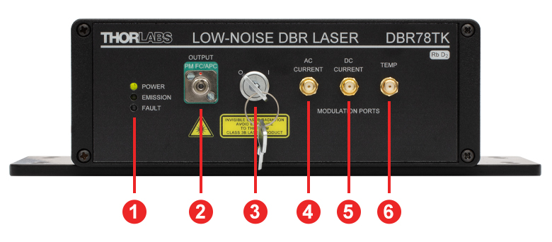
Figure 4.1 DBR78TK Turnkey DBR Laser Front Panel
| Front Panel | |
|---|---|
| Call Out | Description |
| 1 | Status Indicator LEDs |
| 2 | Laser Output Port (FC/APC, 2.0 mm Narrow Key, PM Fiber Output) |
| 3 | Laser Enable Key |
| 4 | AC Current Modulation Input (SMA Female) |
| 5 | DC Current Modulation Input (SMA Female) |
| 6 | Temperature Control Modulation Input (SMA Female) |
| Back Panel | |
|---|---|
| Call Out | Description |
| 1 | RS-485 Communication (DB-9 Male) |
| 2 | USB Communication (USB Mini-B) |
| 3 | Remote Interlock Pin (2.5 mm Mono Phono Female) |
| 4 | Power Switch |
| 5 | DC Input (M8 Connector for the DS12 Power Supply) |
DBR78TK and DBR79TK Laser Pin Diagrams
All Modulation Inputs
SMA Female

Input Voltage: -5 V to 5 V
Input Impedance: 1 kΩ
See the Specs tab for more information.
RS-485 Communication
9-Pin Male D-Sub Connector 
| Pin Assignment | |
|---|---|
| Pin | Output Signal |
| 1 | RS-485 Half-Duplex T/R+ |
| 2 | RS-485 Half-Duplex T/R- |
| 3 | Not Connected |
| 4 | Not Connected |
| 5 | Ground |
| 6 | Not Connected |
| 7 | Ground |
| 8a | Do Not Connect |
| 9a | Do Not Connect |
Click to Enlarge
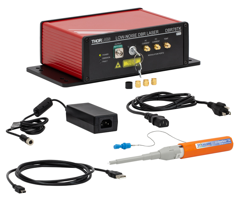
Figure 6.1 DBR78TK Laser System and Accessories
ECL, DFB, VHG-Stabilized, DBR, and Hybrid Single-Frequency Lasers

Click to Enlarge
Figure 7.1 ECL Lasers have a Grating Outside of the Gain Chip
A wide variety of applications require tunable single-frequency operation of a laser system. In the world of diode lasers, there are currently four main configurations to obtain a single-frequency output: external cavity laser (ECL), distributed feedback (DFB), volume holographic grating (VHG), and distributed Bragg reflector (DBR). All four are capable of single-frequency output through the utilization of grating feedback. In addition, an ECL can be combined with a fiber Bragg grating (FBG) to create a hybrid design. However, each type of laser uses a different grating feedback configuration, which influences performance characteristics such as output power, tuning range, and side mode suppression ratio (SMSR). We discuss below some of the main differences between single-frequency diode lasers.
External Cavity Laser
The External Cavity Laser (ECL) is a versatile configuration that is compatible with most standard free space diode lasers. This means that the ECL can be used at a variety of wavelengths, dependent upon the internal laser diode gain element. A lens collimates the output of the diode, which is then incident upon a grating (see Figure 7.1). The grating provides optical feedback and is used to select the stabilized output wavelength. With proper optical design, the external cavity allows only a single longitudinal mode to lase, providing single-frequency laser output with high side mode suppression ratio (SMSR > 45 dB).
One of the main advantages of the ECL is that the relatively long cavity provides extremely narrow linewidths (<1 MHz). Additionally, since it can incorporate a variety of laser diodes, it remains one of the few configurations that can provide narrow linewidth emission at blue or red wavelengths. The ECL can have a large tuning range (>100 nm) but is often prone to mode hops, which are very dependent on the ECL's mechanical design as well as the quality of the antireflection (AR) coating on the laser diode.

Click to Enlarge
Figure 7.2 DFB Lasers Have a Bragg Reflector Along the Length of the Active Gain Medium
Distributed Feedback Laser
The Distributed Feedback (DFB) Laser (available in NIR and MIR) incorporates the grating within the laser diode structure itself (see Figure 7.2). This corrugated periodic structure coupled closely to the active region acts as a Bragg reflector, selecting a single longitudinal mode as the lasing mode. If the active region has enough gain at frequencies near the Bragg frequency, an end reflector is unnecessary, relying instead upon the Bragg reflector for all optical feedback and mode selection. Due to this “built-in” selection, a DFB can achieve single-frequency operation over broad temperature and current ranges. To aid in mode selection and improve manufacturing yield, DFB lasers often utilize a phase shift section within the diode structure as well.
The lasing wavelength for a DFB is approximately equal to the Bragg wavelength:

where λ is the wavelength, neff is the effective refractive index, and Λ is the grating period. By changing the effective index, the lasing wavelength can be tuned. This is accomplished through temperature and current tuning of the DFB.
The DFB has a relatively narrow tuning range: about 2 nm at 850 nm, about 4 nm at 1550 nm, or at least 1 cm-1 in the mid-IR (4.00 - 11.00 µm). However, over this tuning range, the DFB can achieve single-frequency operation, which means that this is a continuous tuning range without mode hops. Because of this feature, DFBs have become a popular and majority choice for real-world applications such as telecom and sensors. Since the cavity length of a DFB is rather short, the linewidths are typically in the 1 MHz to 10 MHz range. Additionally, the close coupling between the grating structure and the active region results in lower maximum output power compared to ECL and DBR lasers.

Click to Enlarge
Figure 7.3 VHG Lasers have a Volume Holographic Grating Outside of the Active Gain Medium
Volume-Holographic-Grating-Stabilized Laser
A Volume-Holographic-Grating-(VHG)-Stabilized Laser also uses a Bragg reflector, but in this case a transmission grating is placed in front of the laser diode output (see Figure 3). Since the grating is not part of the laser diode structure, it can be thermally decoupled from the laser diode, improving the wavelength stability of the device. The grating typically consists of a piece of photorefractive material (typically glass) which has a periodic variation in the index of refraction. Only the wavelength of light that satisfies the Bragg condition for the grating is reflected back into the laser cavity, which results in a laser with extremely wavelength-stable emission. A VHG-Stabilized laser can produce output with a similar linewidth to a DFB laser at higher powers that is wavelength-locked over a wide range of currents and temperatures.

Click to Enlarge
Figure 7.4 DBR Lasers have a Bragg Reflector Outside of the Active Gain Medium
Distributed Bragg Reflector Laser
Similar to DFBs, Distributed Bragg Reflector (DBR) Lasers incorporate an internal grating structure. However, whereas DFB lasers incorporate the grating structure continuously along the active region (gain region), DBR lasers place the grating structure(s) outside this region (see Figure 4). In general a DBR can incorporate various regions not typically found in a DFB that yield greater control and tuning range. For instance, a multiple-electrode DBR laser can include a phase-controlled region that allows the user to independently tune the phase apart from the grating period and laser diode current. When utilized together, the DBR can provide single-frequency operation over a broad tuning range. For example, high end sample-grating DBR lasers can have a tuning range as large as 30 - 40 nm. Unlike the DFB, the output is not mode hop free; hence, careful control of all inputs and temperature must be maintained.
In contrast to the complicated control structure for the multiple-electrode DBR, a simplified version of the DBR is engineered with just one electrode. This single-electrode DBR eliminates the complications of grating and phase control at the cost of tuning range. For this architecture type, the tuning range is similar to a DFB laser but will mode hop as a function of the applied current and temperature. Despite the disadvantage of mode hops, the single-electrode DBR does provide some advantages over its DFB cousin, namely higher output power because the grating is not continuous along the length of the device. Both DBR and DFB lasers have similar laser linewidths. Currently, Thorlabs offers only single-electrode DBR lasers.
Ultra-Low-Noise Hybrid Laser
Thorlabs Ultra-Low-Noise (ULN) Hybrid Lasers each consist of a single angled facet (SAF) gain chip coupled to an exceptionally long fiber Bragg grating (FBG). They are designed to create a laser cavity, similar to an ECL, through the length of fiber. This cavity provides the ULN hybrid laser with a very narrow line width on the order of 100 Hz and low relative intensity noise of -165 dBc/Hz (typical). The FBG reflects a portion of the light emitted from the gain medium while remaining thermally isolated from it. The grating period can be changed by introducing thermal stress to the fiber, allowing users to temperature tune the laser output while being able to independently stabilize the gain medium's temperature. Because the laser's configuration provides excellent low-noise performance, it is likely the laser will not be the limiting factor at low-noise levels. It is critical to monitor the laser's environment to limit external noise contributions like acoustic and seismic vibrations, as well as driving the laser with a low-noise current source.
Click to Enlarge
Figure 7.5 Thorlabs Hybrid Lasers have a Fiber Bragg Grating Coupled to the Active Gain Medium
Conclusion
ECL, DFB, VHG, DBR, and hybrid laser diodes provide single-frequency operation over their designed tuning range. The ECL can be designed for a larger selection of wavelengths than either the DFB or DBR. While prone to mode hops, it provides narrow linewidths (<1 MHz). In appropriately designed instruments, ECLs can also provide extremely broad tuning ranges (>100 nm).
The DFB laser is the most stable single-frequency, tunable laser configuration. It can provide mode-hop-free performance over its entire tuning range (<5 nm), making it one of the most popular forms of single-frequency laser for much of industry. It has the lowest output power due to inherent properties of the continuous grating feedback structure.
The VHG laser provides stable wavelength performance over a range of temperatures and currents and can provide higher powers than are typical in DFB lasers. This stability makes it excellent for use in OEM applications.
The single-electrode DBR laser provides similar linewidth and tuning range as the DFB (<5 nm). However, the single-electrode DBR will have periodic mode hops in its tuning curve.
Hybrid lasers can be used to achieve extremely low-noise signals. In order to take advantage of this characteristic, the laser must be isolated from unwanted noise sources, such as acoustic and seismic vibrations and drive current noise.
| Posted Comments: | |
| No Comments Posted |

 ZoomClick to Enlarge
Click for Data
Figure G1.1 Example temperature and current tuning for a DBR78TK laser system operated at the factory-set conditions.
- Central Wavelength of 780 nm or 795 nm
- >30 mW Output Power at the Rb D2 (Item # DBR78TK) or D1 (Item # DBR79TK) Nominal Vacuum Transition
- >25 GHz DC Current Modulation Tuning Range
- 2.4 nm Temperature Tuning Range
- <400 kHz Lorentzian Linewidth
- -150 dBc/Hz Typical Relative Intensity Noise (RIN)
- 30 dB Typical Side-Mode Suppression Ratio (SMSR)
Thorlabs’ DBR78TK and DBR79TK lasers are turnkey, low-noise laser systems that integrate a Distributed Bragg Reflector (DBR) laser diode in a butterfly package with a high-performance, low-noise driver and temperature stabilization inside of a benchtop housing. The DBR78TK is centered at 780.2 nm, corresponding to the D2 atomic transition line of rubidium (Rb), while the DBR79TK is centered at 794.8 nm, aligned with the D1 transition line of rubidium. The temperature of the laser case is stabilized through a third temperature stabilization circuit to provide long-term power and wavelength stability when the system is used in standard laboratory environments. See the blue info icon (![]() ) in Table G1.2 for typical performance specifications.
) in Table G1.2 for typical performance specifications.
| Table G1.2 Specifications | |||||||||
|---|---|---|---|---|---|---|---|---|---|
| Item # | Info | Center Wavelength | Output Powera,b |
Linewidthc | DC Current Modulation Tuning Range (Typical) | Relative Intensity Noise (RIN)d |
Side-Mode Suppression Ratio (SMSR) |
Mode-Hop-Free Single-Frequency Region |
Temperature Tuning Range |
| DBR78TK | 780.2 nm | >30 mW | <400 kHz | 39 GHz | -150 dBc/Hz | >30 dB (Typ. 50 dB) | Continuouse | 2.4 nm | |
| DBR79TK | 794.8 nm | 26 GHz | Continuousf | ||||||